 Over the last while I’ve been having a problem with excess humidity in the shower rooms. Imagine that, the builder never put in extractor fans when the house was built! Anyway, I could put in those fancy extractor fans with the built in timers or humidity sensors, but I decided to do things the more interesting way, by using a small computer to read the values from a humidity sensor in each room, and based on the readings, turn on the fan until the humidity was reduced to an acceptable level.
I happened to have several spare Raspberry Pi’s lying around, so that’s what I used for this project. But there’s nothing stopping you using an Intel Edison, Intel Galileo, Creater CI20, Beagleone Black, Beaglebone green, etc. Use whatever you’re comfortable with.
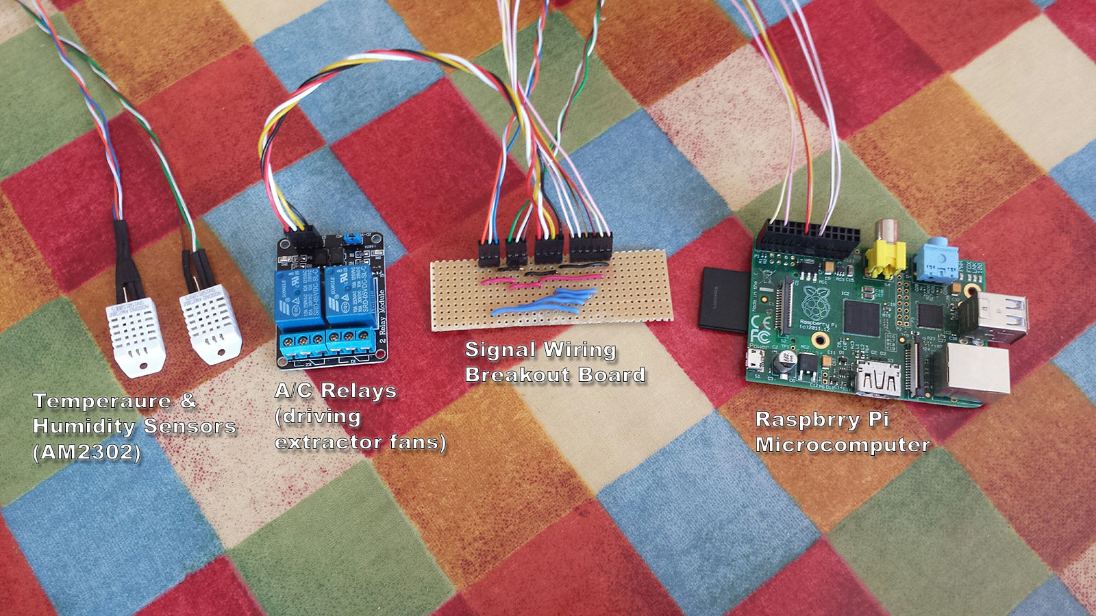
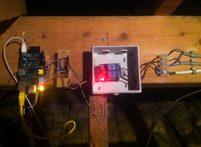
Here’s a picture of the wiring before installation in the attic.
 (click on image to see full size)
From left to right in the image:
- AM2302 Temperature and Humidity sensors. These will be placed near the ceiling of each shower room (not in the shower cubicle) in a place that’s easy feed the wires up to the attic, where they can be connected to the wiring breakout board. I’ll secure the sensor to the wall with a small screw.
- Dual A/C Relay board. This board will be used to driver the mains power required for the wall mounted extractor fans. The fans are designed to go into a 120mm hole, and it took most of the weekend with an enormous drill to make the required holes to take the fans.
- Rather than make a (very complicated cable) to connect everything to the GPIO header on the Raspberry Pi, I decided to break it down to simpler cables and use a breakout board to bring them together. For the sensors, it’s a couple of 3-way cables. The Relay board takes a 4-way, and then 6 wires going back to the Pi is 6-way on one end and a 26-way on the GPIO header end.
- Then there’s the Raspberry Pi to control it all.
The sensors and the Relay board both require 5V power suppy to operate, so that’s one of the main tasks of the breakout board – to distribute 5V and GND to each of the pin headers. Then there’s just the data signal from the sensors, and the two relay activation signals for the Relay board. Quite a straightforward circuit, really.
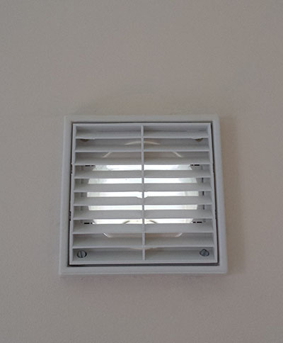
Here we see the wall mounted extractor fan, it’s a 230V unit, requires a 120mm hole all the way through the two leaf’s of 100mm concrete blocks, and there’s a vent on the outside that opens when air is pushed out. In the picture, you can also see the bad paint job after I chased the wall to put in the mains cable to feed power to the fan. The mains cable runs through white plastic conduit, then the gaps filled with a sand/cement mix, then the surface smoothed with multi-purpose filler, and sanded down. Then painted. The mains cable will be fed back to the Relay board in our humidity system.

Don’t worry, It does look OK once it’s painted properly… Here’s another vent done the same weekend, but finished properly 🙂
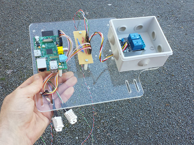
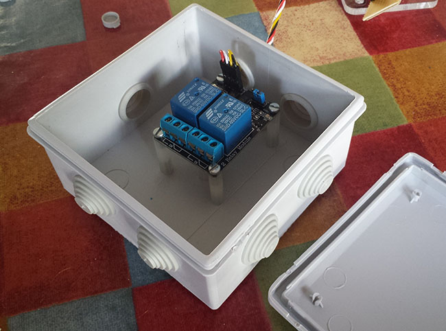
I’ve also isolated all the mains components in a box with a cover.
And then mounted everything on a sheet of acrylic with stand-offs. This will allow an easy mounting to a rafter in the attic.
And here’s a really bad picture of the setup in it’s final location, with everything wired up. The fans worked first time, I guess it pays to double and triple check everything, especially if you’re not used to dealing with mains voltages… 🙂
I still need to do some tidy up, but at least it’s working…
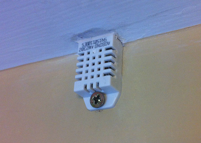
And here’s the mounted AM2302’s on the wall right by the ceiling. The wires go straight up through the plasterboard.
The software I’m using is a mix of a sample ThingSpeak python script and Adafruit’s example for reading an AM2302, plus WiringPi and Wiring-Python to drive the Relay GPIOs. The temperature and humidity are read every minute and published to ThingSpeak, where I can monitor the historical data, and in the same script has very simple check for each room whether the Humidity goes above 90%, in which case I switch on the fan, and if it goes below 80%, I switch off the fan. It’s a very crude algorithm, but I’ll come back to that when the system is settled in a bit.
And here’s some visualisations after a few hours. It shows the Humidity in the shower room before I did a couple of experiments, and ran the shower for a couple of minutes once with the extractor fan on, and finally with the extractor fan off.
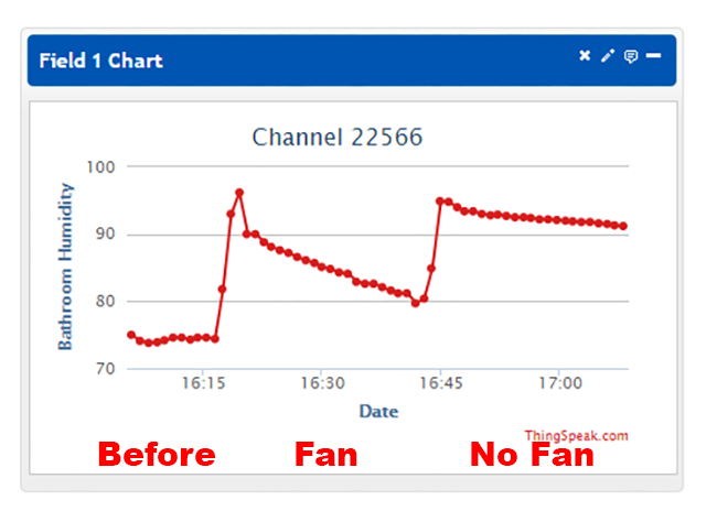
There are two ‘shower’ events here, where I turned on the shower for a couple of minutes to introduce some damp air into the room. The sharp rise in humidity is obvious in both cases. In the first case, the extractor fan was enabled, and in the second case, the extractor fan was disabled. The section where the fan was enabled shows a good rate of decline in humidity after a shower was stopped, so I feel good that I went to the trouble of installing the extractor fans. The very slow decline in humidity for the second test shows why I’m having problems with humidity in those rooms. 🙂 And the Microcomputer to control it? Maybe a bit over the top, but I sure do have good data to show for it!
The live data can be seen on one of my ThingSpeak channels here.
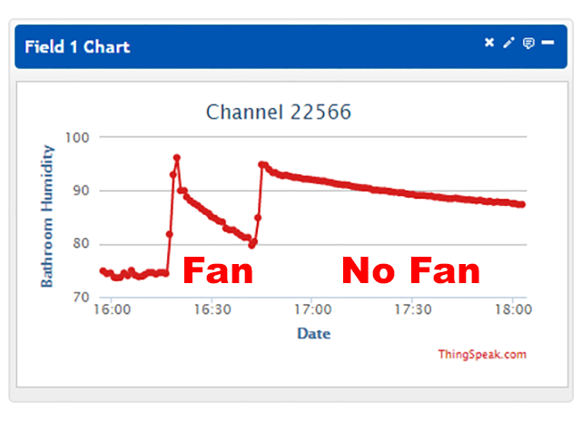
Edit: Here’s an even better graph taken a couple of hours later…
Dave. Again excelent poject. May i ask how u kep raspberry pi supplied? Battery or transformer from main?
Mateusz,
Thanks for the comment! In the dark picture, you can see a white cable feeding into the micro-USB socket. The white cable is a standard USB cable, and it plugged a wall socket charger I had lying around. I have a few mains sockets in the attic, so I used one for the Pi.
Dave.
Hi Dave,
Interesting approach. We have an extractor which we switch on when having a shower.
To get rid of all the steam, it needs to be left on for a while afterwards … and that’s where
the problem is: we forget to turn it off 🙁
So I was thinking of doing something similar, except with Arduino, DHT22 and ESP8266.
Was thinking also about using a little in-line flow meter:
http://www.ebay.com/itm/1-30L-min-1-2MPa-1-2-Hall-Effect-Flowmeter-Control-Water-Flow-Sensor-Arduino-/161129523876
in the hot-water pipe which could trigger the extractor fan – so that the extractor comes on
and is already running *before* the room starts filling up with steam.
Then the Arduino would turn it off when the humidity drops down to normal.
(the ESP8266 isn’t actually needed, but it would turn it into an IoT device)
For ‘controller’ jobs like this, I prefer Arduino. It’s a fraction of the price and over time
I find Arduino to be more stable and doesn’t need to be rebooted (like the RPI).
Thanks.
Best regards,
Niall.