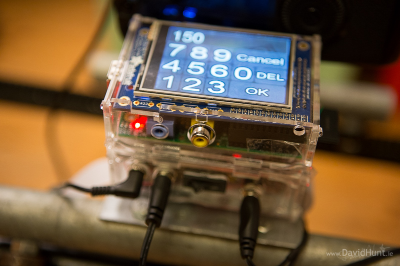
 So here’s my latest Raspberry Pi project. It uses the PiTFT Mini Kit, which is a 320×240 2.8″ TFT display and Touchscreen from Adafruit Industries that fits neatly onto my Raspberry Pi, to control a user interface to drive the back-end time-lapse script I showed you in a previous blog article.
In that article, Lapse Pi -Motorised Time-lapse Rail with Raspberry Pi, I showed you some simple python code to drive the time-lapse rail by running the script from a laptop or smartphone capable of ssh’ing into the Raspberry Pi.
Update: Be sure to check out the latest revision based on an ESP8266 MCU with Wifi Hotspot.
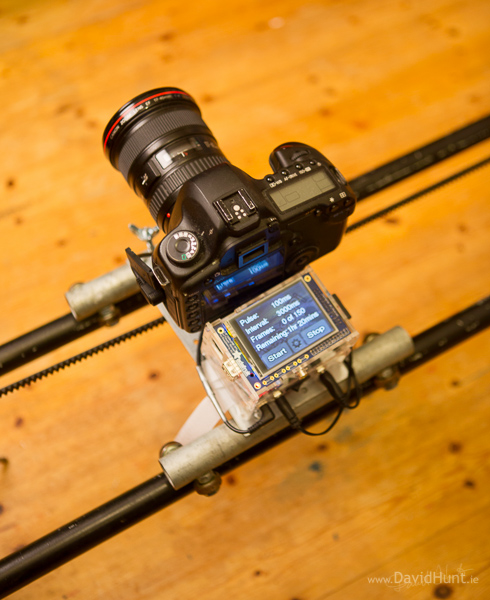
The PiTFT allows me to take the project up a notch, by putting the user interface right on the Raspberry Pi, so no external device or connectivity is needed. Here’s a picture of the setup.
Functionality
The User interface allows you to:
- position the dolly on the rail via the motor control buttons
- change the motor pulse duration between shots
- change the delay between shots
- change the number of shots
- see what time is left for the current sequence
- start and stop the time-lapse
And it’s all done using a few simple screens with a simplistic, easy-to-use touchscreen user interface. The following video shows it all in action.
[embedplusvideo height=”375″ width=”600″ editlink=”http://bit.ly/1mrsFGt” standard=”http://www.youtube.com/v/jxQcbp0qXQs?fs=1&vq=hd720″ vars=”ytid=jxQcbp0qXQs&width=600&height=375&start=&stop=&rs=w&hd=1&autoplay=0&react=1&chapters=¬es=” id=”ep7041″ /]
As you can see in the video, there’s now a motor controller circuit in the mix to allow me to change the direction of the motor from software, rather than having to use a switch.
Controller Parts
- $35 – Raspberry Pi
- $35 – PiTFT
- $2 – DC-DC converter
- $8 – Motor Controller (Dual H-Bridge circuit)
- $10 Misc Connectors, transistors, etc.
- $10 – 2 cheap acrylic Pi cases from eBay
Total for the controller – round about $100.
–EDIT–
There’s now a guide covering the hardware in more detail at learn.adafruit.com
–EDIT–
Originally I had a laptop connected to the Pi via Wifi, and later on I had a smartphone do the same, but then I got my hands on a PiTFT, a shield that sits neatly on top of the Raspberry Pi. When I saw it on the Adafruit website, I knew I had to be quick, so 5 minutes later I had one on order, and five minutes after that they were out of stock. Shipping took a while, the order went in before Christmas, and to be fair to Adafruit, the package shipped the next day, but it took over a month to get here from the States. Small packages are usually a lot quicker than that.
Anyway, when it arrived I started researching the best method to develop a Time-lapse User Interface. I looked a TKinter, and did a few sample apps. This was more suited to Xwindows development, and the controls were all very small and difficult to use with just your finger. Limitations in the controls also meant it was difficult to size them up to be suitable for the 2.8″ display. So I came to the conclusion that TKinter was not a suitable development environment for my needs.
Then I came across the excellent “DIY WiFi Raspberry Pi Touchscreen Camera” tutorial on Adafruit’s website by Phil Burgess. It’s implemented using PyGame, and the GUI looked really slick and simple to use, so I got my hands on the software, installed it and got it up and running. And the amazing thing is that it was all done in about 647 lines of Python! So, I dove into the guts of the code and saw that it was a very elegant method using PyGame to display icons on the screen and allow actions to happen when those icons are touched. Ideal for a simple user interface of a couple of screens, which is what I’d planned for the time-lapse GUI. So I set about tearing it down and adapting it for my needs.
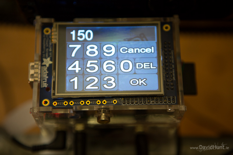
One of the main challenges was doing a numeric keypad entry. That would require lots of icons, and a method of displaying what the user was typing. So I started on that one. Photoshop is great for throwing icons together, and putting fancy effects on fonts, so I used something similar to the Adafruit Camera’s font, a white font with a thick black stroke, and a checkered, semi-transparent background for the touchable icons.
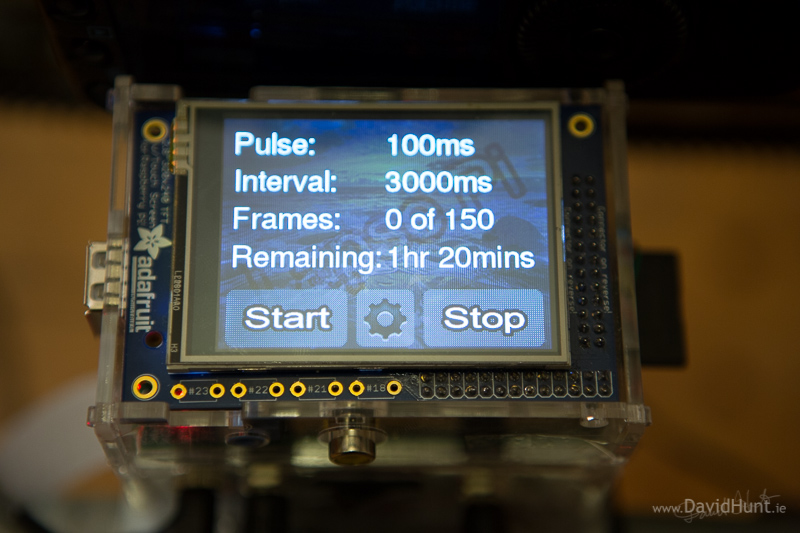
Next was the screen for the main display, which is what’s shown to the user when the time-lapse is running. This allows the user to start/stop the time-lapse, with another button for settings. Everything else on the screen is just information on the current status of the time-lapse.
The final screen is where the use can change the settings. For this initial version of the GUI, there’s only four settings that can be changed:
- The length of the pulse we send to the motor
- The delay before the next shot
- The number of shots
- The direction of the motor
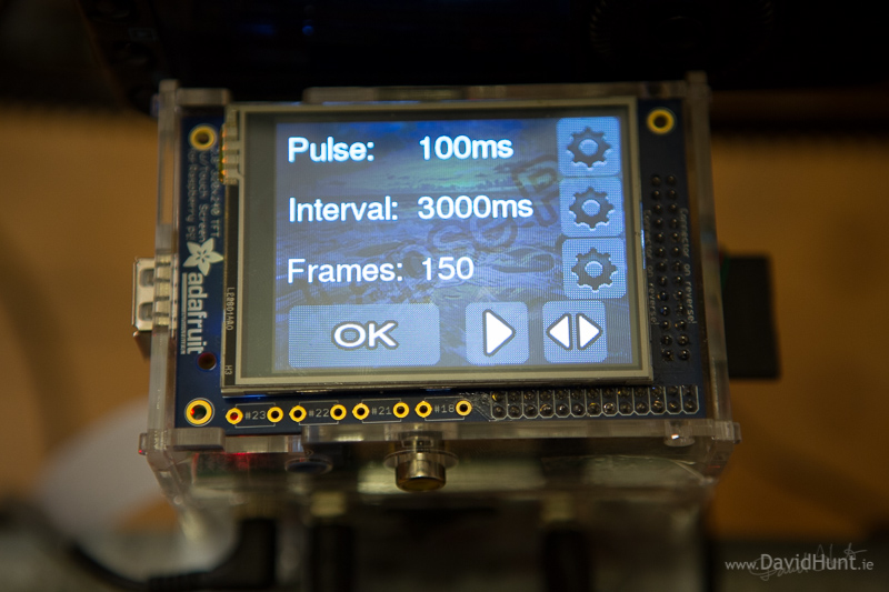
For each numeric setting, there’s a touchable button which brings the user to the numeric keypad entry, where they can change the value passed in.
There’s also two buttons for motor control, one for motor direction, and one to drive the motor. This is used to get the camera dolly into the correct position at the start of the time-lapse.
Once you start a time-lapse running, it runs in a background thread, so you can continue to move about the screens and change settings. If you change any of the settings, they will immediately be reflected in the running time-lapse. I’m not so sure this is a good idea, so I might change that. Also, the motor buttons can also affect the movement of the dolly, so I think I’ll disable those buttons while the time-lapse is running.
The code is based on the Adafruit PiTFT Camera tutorial by Phil Burgess, and I’ve taken the user interface portions of his cam.py application and used them for my time-lapse controller GUI, which I call lapse.py. Fits nicely with the name of the project, don’t you think? 😉
The Code
The code is available here on GitHub, with installation instructions and prerequisites. It also includes all the icons needed for the touch screen interface.
Documentation is generated from the docs directory on Github, but can be read here on ReadTheDocs.org. This includes a User Guide.
Previous time-lapses
Here’s some of my recent work. This was not done with the touch version of the time-lapse controller, but it does give you an idea of what can be done with this system. Most of the footage in this video was shot using a Raspberry Pi controlling the time-lapse rail.
Raspberry Pi is a trademark of the Raspberry Pi Foundation
About the Author:
By day I’m a senior embedded Linux software engineer. In my spare time, I take pictures, and play with gadgets and technology.
Twitter: https://twitter.com/climberhunt @climberhunt
Facebook: https://www.facebook.com/davidhuntphotography
Be sure to check out my other Raspberry Pi related articles, and if you like, you can subscribe by entering your email address at the top right of the page. 🙂
Donations
If you like this project, and would like help support it’s continued development, and the development of future projects (this Making is an expensive hobby!), then feel free to donate something using the following PayPal button:
Other Related Posts:
- Raid Pi – Raspberry Pi as a RAID file server
- Drop Pi – Water Droplet photography with Raspberry Pi
- Macro Pi – Focus Stacking using Raspberry Pi
- Camera Pi – DSLR Camera with Embedded Computer
- Lapse Pi -Motorised Time-lapse Rail with Raspberry Pi
Great video Dave 🙂 Reminds me of the sort of stuff they do on programmes like Frozen Planet etc. every bit as good too. That must be weeks worth of work. Brilliant stuff.
Thanks, Alex! Yes, dozens of hours over several weeks, all right! 🙂
Great stuff again as usual David. Something I am definately going to do, but using my own design 2.8″TFT (of course 😉 ).
Texy
would this work if i done it exactly the same without the camera dolly (like dont have the motor plugged in?)
Yes, Lewis. You could just have the circuit to drive the shutter on the camera, and leave out the motor driver.
Hi David,
I am attempting to covert your python code for my TFT display board, which although is based on the same TFT module, uses a GPIO pin for the backlight rather than via a control bit like the adafruit you are using. I,ve got the screen working OK, but for some reason, I cannot get any life out of the configuration page – pressing any of the ‘buttons’ does nothing, including getting back to the main page. Note I haven’t connected up any additional hardware at this stage, but that shouldn’t matter as they are connected to the Pi’ outputs anyway. So i am unable to change the Pulse, Interval or Frames value as it doesn’t enter the numeric keypad. I haven’t needed to change any of that code, so i am a bit stumped.
Texy
Texy, stick in a print statement around line 425 where it gets the MOUSEBUTTONDOWN event. If you’re not getting the event, then its something to do with the driver or touchscreen drivers.
Thank you for the reply David.
I get a print statement when i press the config button from the main menu, but nothing after that……..
Just to confirm i have 2 issues, which may be related.
When the program first runs, I can START with the default parameters. I can also STOP it. However I cannot restart it, or enter the configuration page thereafter.
When the program first runs, I can enter the configuration page, but not exit it, or change any parameters.
Texy
Can you try running it from an ssh session? You’ll see if it bombs out, and the screen may not be going back to the console if it is crashing.
You might have it ctrll-c during screen init when starting remotely.
That’s how I have been connected, but I have also tried locally.
It doesn’t appear to bomb out at all. FYI I have also modules the code to allow local quitting by hitting the escape key with the keyboard. That gives me a thought – perhaps having the keyboard connected is causing the problem. I’ll try removing it….
Texy
OK, finally fixed the problem – which wasn’t a fault in your code 😉
Your code uses GPIO17 for the shutterpin, but my screen uses that for the touch panel IRQ, so it clashed. Once I changed the shutterpin GPIO to an unused one it all sprang into life.
One other thing I,ve noticed is that when the sequence has finished, and you want to start it again, you need to STOP it in order to reset the FRAMES to 0.
Thanks for your support,
Texy
That’s great Texy. Good to hear! I’ll make a note of the counter reset problem, and push a fix to GitHub later.
Feel free to suggest any other improvements or let me know of any bugs. 🙂
Will do once i get it up and running. The electronics side of things I have no problem with, however I can’t use my hands for toffee, so the rails, trolley etc are more of a challenge for me.. Currently looking into Meccano as an option …..
Incidently i’d like to make a donation, but the Donate button just goes to the paypal website, at least it does for me using Chrome.
Texy
I changed a few things today. Fixed the bug Texy mentioned above, now can start repeatedly. Timings were off, and Remining field is now being updated. Also change the Play/Reverse mechanism for the motor to be a simple Left/Right. Makes more sense to me.
All changes here: https://github.com/climberhunt/LapsePiTouch
Hi David,
Your timelapses look amazing! I’ve tried creating some of my own using the Pi and the camera board. However, I haven’t found a method of compiling them into a video that I’m happy with yet.
http://www.andresworld.co.uk/code/creating-a-timelapse-video-using-mencoder-and-ffmpeg-on-a-mac/
How do you go from jpeg to avi? Do you use command line tools or proprietary software? Any code you can share would be much appreciated! Thanks!
Andrew, I’ve one word for you – “VirtualDub”. It’s a great little piece of software, ideal for assembling frames into videos. Saves out as AVI, but you can convert afterwards using whatever software you like.
Dave.
Oh, and to edit the videos I use Cyberlink PowerDirector. The €89 version.
You can use the pi to compile video from jpg too, using mencoder.
Of course it may be slower than your average PC…..
Texy
Should be ok for doing it on thumbnails, which would be fine for checking the progress of the time-lapse 🙂
Hi David,
Saw this article on the Raspberry Pi home page, just wanted to say how much I loved this timelapse, absolutely stunning and no matter how many times I watch it, I never got bored.
Great work with the Pi code too 😛
Thanks Megan. I appreciate the comment! 🙂
Great stuff David !!! Thanks for sharing. I m going to add soon this TFT to my Pi. (once installer on top of the Pi can you still access the GPIO with a console cable in order to access the Pi from another computer?) I set up an LCD screen on it already to check the IP at boot as well as other controls and alerts as I m shooting RAW+JPG, store RAWs on a hard disk, send over the jpgs to my server. Also, as my timelapses run on specific days of week and times, I wrote a cronjob to start at boot too. (Python is another option for this but I like to KISS). In order to save battery life I wired the whole set to a timer. My camera is USB connecter to a hub powering the Harddisk as well. I have a question about the switch you installed to power ON/OFF your whole device?: is it performing a soft shutdown or a hard one? In case of a hard shutdown, is not it a problem for the Pi to switch it off that way? Best and cheers !!! Laurent
Yes, the PiTFT has another GPIO connector on one side, so you can pass through the GPIO pins from the Pi to external devices. That’s what I’ve done here to control the motor and camera. You are right about the hard shutdown, I’m in the process of adding a button the TFT (the buttons arrived last week), so that when I press it, it will do a soft shutdown, then I flick the switch to cut power.
Great!!!
Actually I am re-building your controller. I want to add some more buttons on the screen and extend the functionality. For this I would like to know how you created the icons. Can you please tell me what kind of font yu used etc?
Chris,
It’s not just a straightforward font, it’s a font I modified in Photoshop. It’s one of the standard fonts, (not sure which, I’ll look at the file later), but I added an outline with the layer attributes (outer glow, I think). The Photoshop file is in a bit of a mess, it consists of multiple layers (1 for each icon), and I saved them out individually as PNGs with the relevant layers active. I might have a go at cleaning up that file and getting it into the GIT repository with all the other stuff, that might make what you’re trying to do easier. Open source AND open artwork! 🙂
Dave.
Hi Dave,
Really fascinated by this project as I have built a time lapse rig myself and am in the process of releasing a new controller firmware update for my original controller + currently working on a 3 axis rig that has traverse, tilt and pan. To date I have been using ATMega chip based controllers (similar to Arduino) but having just brought a Rpi B for another project I started to think about a pi based HyperLapse controller with touch screen and low and behold I found yours. Thanks for sharing this info as you have taken many hours off my development time. What a fantastic job you have done – looking forward to having a go with this controller and seeing more of your work.
All the best, Steve
Hi Dave!
Wow!! I love it, the touch screen looks really class! You are a genius!
I’ve finished my slider, not patch on yours since I used a pre-made controller which isn’t ideal…
I’m writing about it on my blog anyway!
Gota get out and do lots of trials!
Your time-lapses are an inspiration, well done!
Oisín
Hey David,
Thank you so much for sharing this. I have one question. I have followed all your steps, but when I launch the lapsePi software, I cannot interact via touch screen. Loading script says “Selected device is not a touchscreen I understand.” Any suggestions? The touchscreen does work otherwise.
Thanks!
Patrick, have you gone through all the PiTFT setup, including the calibration steps?
http://learn.adafruit.com/adafruit-pitft-28-inch-resistive-touchscreen-display-raspberry-pi/touchscreen-install-and-calibrate
Dave.
Hi,
That may be because of having a mouse or keyboard connected. It is related to the eventX number will be different due to additional input devices fitted.
Texy
Hey David Im in the process of building at time lapse rig, I can do the construction and programming but alittle lost at the electrical side. can you send me pictures of the wiring. Like how you connected to the GPIO pins on the PiTFT. I have read though the adafruit write up but picture of the all the wiring would be extremely helpful. Thank you so much
Luke,
I’m afraid my wiring is very messy, which is why I didn’t show pictures of it on the blog, and made up diagrams instead. it wouldn’t do much good to see the wiring in it’s current state. Also, I’ve the whole thing sealed up with tape, and it would be quite a bit of work to take it all apart. I suggest doing one GPIO at a time, test the output with a LED, then check it with either the motor driver or transistor. Step by step, as they say! 🙂
Dave.
Hi David. Awesome project. Forgive my ignorance. I’m a noob at all things pi. Is there a way to run this program without a touchscreen (just using the HDMI monitor)? What modifications to I need to make? Thanks again. Truly fantastic.
Josh, Interesting idea. I don’t see why not. Although it will look rather small on a bigger screen, with the user interface appearing in the corner or middle of the screen at 320×240 pixels. All you’d need to do is not set up the touchscreen in the boot parameters, and have the mouse used instead of the touchinput device. It’s very do-able. 🙂
Dave.