 Here’s a very basic howto on switching a DC motor on/off with a Raspberry Pi using a transistor.
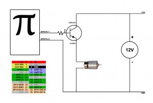
The circuit:
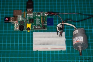
Notice that the GPIO numbers for the pins don’t relate to the physical pins on the GPIO header, so take care to map them correctly when wiring and programming. The transistor acts as a simple switch, and when the GPIO pin is a zero volts, the collector to emitter is effectively an open-circuit, not allowing any current to flow through the motor. However, when the GPIO pin is 3.3v, the current can then flow from collector to emitter, switching on the motor. Also, stick in a resistor to reduce the amount of current drawn from the GPIO pin. 1K should be fine.
The Setup:
The Software:
To enable the GPIO pins, I used gpio-admin, a small program to export the gpio pins for use. It’s available here: https://github.com/quick2wire/quick2wire-gpio-admin
Script to enable and toggle GPIO pin:
#!/bin/sh
#
gpio-admin export 4
cat /sys/devices/virtual/gpio/gpio4/valuee
cho out > /sys/devices/virtual/gpio/gpio4/direction
echo 0 > /sys/devices/virtual/gpio/gpio4/value
while [ 1 ]
do
        echo "Turning motor on..."
        echo 1 > /sys/devices/virtual/gpio/gpio4/value
        sleep 2
        echo "Turning motor off..."
        echo 0 > /sys/devices/virtual/gpio/gpio4/value
        sleep 2
done
Here’s a video of the setup in operation:
[embedplusvideo height=”365″ width=”450″ standard=”http://www.youtube.com/v/8Tt4NYeWEoc?fs=1″ vars=”ytid=8Tt4NYeWEoc&width=450&height=365&start=&stop=&rs=w&hd=0&autoplay=0&react=1&chapters=¬es=” id=”ep2179″ /]
The above circuit will only drive the motor in one direction. The motor I have will go in either direction, but I need to switch the polarity of the 12V power supply. I might get to that in the near future.
Raspberry Pi is a trademark of the Raspberry Pi Foundation


Oh, this sounds cool!
So, we could port the Dolly Engine MX2 code to the Raspberry Pi and control the camera via USB. I’m already considering to get a Raspberry Pi and replace the Arduino in my Bulb Ramper (Brampuino 1-X).
Nice and simple, but aren’t you asking for your Pi to be fried by having virtually no protection on the GPIO pins?
Even just something to protect against back EMF from the motor, or am I being paranoid?
What eletrical components do you use?
Some random transistors I recovered out of a busted PC power supply. 🙂
Hi Dave,
I am surprise that an electronician didn’t already suggest you that you connection to the motor is unusual.
The standard position of a load in a power circuit with a transistor is in the collector branch, between the transistor collector and the power supply.
The main drawback is that in your case, the voltage on the motor can’t be higher that the command voltage from you Raspberry Pi (probably 5V) minus tu Vbe voltage between the transistor base and the transistor emitter (0.6V). Then a resulting voltage of around 4.4V.
Two advantages on changing the system:
– the voltage on the motor could be closer to 5V because the Vce tension is lower than 0.6V
– the power supply for the motor can be different from the power supply for the Pi. Then you could drive a 12V motor.
Didier.
Oups, some typo in my comment and also I can see that you drive your motor already with 12V. Then if you measure the real voltage no the motor, you will see that it is far from 12V and close to the 3V you apply on the base of the transistor.
Didier.