Page 1 – The plan and some construction shots and info
Page 2 – More Construction
Page 3 – The Circuit, the Code, plus a video of the rig in action
The Circuits
I only needed two GPIO pins, one for driving the DC Motor, and the other for triggering the shutter of the camera. I used pins 17 and 18 (plus the GND pin, of course). Since the DC Motor is 12V, I used a battery pack that takes 8 AA batteries, giving me about 11 volts, which works fine, and it’s more portable than an AC power supply. See my previous posts for a portable 5V power solution for the Raspberry Pi. It’s basically a DC-DC converter that I salvaged from an iPhone car charger, which converts anything from 7-13 volts input to a nice stable 5 volt output.
There’s a couple of (very) simple circuits to build, one for the solenoid, and one for the shutter release of the camera. First, the motor circuit. The flywheel diode to protect the transistor against the inductive spike from the motor when it keeps going after the pulse has dropped), I don’t actually have a diode in my build, but I’m told it’s a good idea to have one. 🙂 You can see the discussion about the flywheel diode in the Water droplet blog article. In both curcuits, a 1K resistor should be fine.

Next, the Shutter Release circuit. This has been tested with a Canon 5D Mark II and Mark III. There are 3 wires in my shutter release cable, usually black, white and red. Black is GND, white is focus and red is shutter release. I’ve called focus pin 2 and shutter release pin 3, with GND being pin 1. I didn’t include a photo of the circuit, as it’s such a mess it wouldn’t inspire confidence. It works, though! 🙂 
–edit–
Per Magnusson let me know of a blog article he’s written while he was developing his own version of the electronics for this project. He’s done a very good write-up here – http://axotron.se/blog/electronics-for-the-lapse-pi-motorised-time-lapse-rail/. What’s particularly interesting is that he describes the tweaks that are needed to drive Nikon cameras. Thanks, Per! 🙂
–edit–
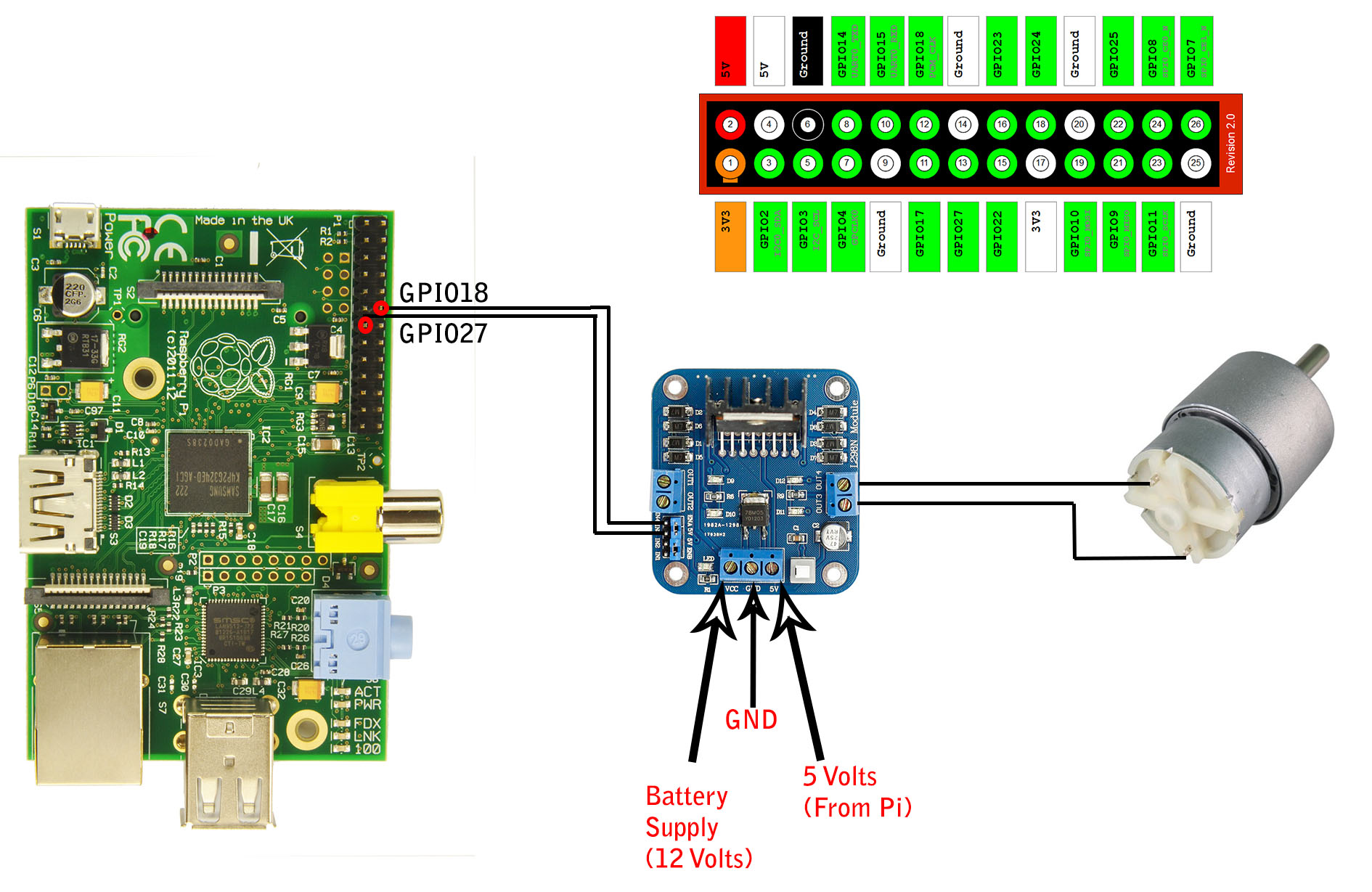
Or, if you’re using a motor controller, here’s a handy diagram for you. GPIO pinouts shown are the ones used in the Lapse-Pi touch version of the controller, but you can change the pins to the ones you’re using on your Raspberry Pi.
The Code
Here’s a small bit of python that should get you going. There’s a bunch of variables at the start of the script to define the length of pulse you send to the motor, the settling time for the motor, etc. Experiment with these to get the optimal settings for your particular time lapse.
import wiring
from time import sleep

shutterpin = 17
motorpin = 18

framecount=5
pulse_length=0.1
settling_time=0.5
shutter_length=2
interval_delay=0.2

gpio = wiringpi.GPIO(wiringpi.GPIO.WPI_MODE_GPIO)
gpio.pinMode(shutterpin,gpio.OUTPUT)
gpio.pinMode(motorpin,gpio.OUTPUT)
wiringpi.pinMode(shutterpin,1)
wiringpi.pinMode(motorpin,1)

for i in range(0,framecount):
    gpio.digitalWrite(motorpin,gpio.HIGH)
    sleep(pulse_length)
    gpio.digitalWrite(motorpin,gpio.LOW)
    sleep(settling_time)

    gpio.digitalWrite(shutterpin,gpio.HIGH)
    sleep(shutter_length)
    gpio.digitalWrite(shutterpin,gpio.LOW)
    sleep(interval_delay)
And finally, here’s a video of the rig in action. It also includes one of the first time lapses I shot with the rig.
[embedplusvideo height=”365″ width=”600″ standard=”http://www.youtube.com/v/cIyb3K8srtc?fs=1&hd=1″ vars=”ytid=cIyb3K8srtc&width=600&height=365&start=&stop=&rs=w&hd=1&autoplay=0&react=1&chapters=¬es=” id=”ep1379″ /]
If you want to be kept up-to-date with my hacks, photos, etc, Join me on Facebook or Twitter, links below.
Raspberry Pi is a trademark of the Raspberry Pi Foundation
About the Author:
By day I’m a senior embedded Linux software engineer working with Emutex Ltd, an Embedded Software Solutions company in Limerick Ireland. In my spare time, I take pictures, and play with gadgets and technology.
Twitter: https://twitter.com/climberhunt @climberhunt
Facebook: https://www.facebook.com/davidhuntphotography
Other Related Posts:
- Lapse Pi Touch – Touchscreen Timelapse Controller
- Raid Pi – Raspberry Pi as a RAID file server
- Drop Pi – Water Droplet photography with Raspberry Pi
- Macro Pi – Focus Stacking using Raspberry Pi
- Camera Pi – DSLR Camera with Embedded Computer
Page 1 – The plan and some construction shots and info
Page 2 – More Construction
Page 3 – The Circuits, the Code, plus a video of the rig in action
Great work – must admit I’m in the process (and may be for some time) of building the same thing -taken some inspiration from the focus stacking project, and got the stepper motor bit working. Now need to build the hardware, though I’m planning to invest in an Igus rail – I presume you’ve seen the Chronos project….
This is incredibly neat! I just have a few questions: What program did you use to render the video? I presume ffmpeg?
Also, how many shots per minute did you take? Thank you!
The frames were stitched together using VirtualDub, which is a great little program for this type of thing.
All sequences were planned for 24 frames per second, so that makes 1440 shots per minute. However, there are a couple of HDR sequences in there, so I did 3 shots for every frame, so that’s 4320 shots per minute. Kinda hard on the DSLR’s mirror mechanism! 😉
very good, will try to make some myself, may use a threaded rod instead of a belt, we’ll see
where did you get the legs? (I’m in Dublin in case you could share where you got them)
did you say where you got the motor from? just curious
If you use threaded bar for this, then when rewinding the dolly, the nut on the threaded bar can overheat and seize, unless you cool it, bit too troublesome that with oil or coolant getting everywhere. Been there.
Legs were in woodies, but they only had 2 left where I got them. Looked like some kind of wall hangers. €1 each!
And eBay for the motor.
Great writeup…where did you get the chrome ‘pipes’?
Mike, Local hardware store, shower curtain rails! 🙂
Dave.
Hello,
I’m thinking that most of the parts you used are familiar to professional photographers, because nearly all of them are a mystery to me! I would love to build one of these, but I don’t have a clue about what these parts are or where to buy them:
skate bearings
dolly tubes
timing belt
mounting plate
Would it be possible to make a list of parts with their original purpose and where you got them from please? Just a wee bit more detail?
Brian,
None of those terms are photographic terns! 🙂
I sourced most stuff from my local DIY store. mounting plate is simply a rectangular piece of steel, which I drilled myself. Tubes are pieces of pipe, timing belt from auto shop, skate bearings from ebay. Research, research, research! 🙂
Dave.
Thanks Dave,
in that case, would it be possible to get a few more pictures of e.g. where the timing belt is connected at each end? (And what is a timing belt when it isn’t used for this job please?)
Thanks!
Brian
Brian,
I’ll try and get a picture of the timing belt clamps. It’s all made with what I had available to hand, or available in the local hardware store.
Wikipedia has a very good explanation of what a Timing Belt is.
Regards,
Dave.
Hi!
Some of the images are just beautiful!
Is it possible to get them in digital format to use them as desktop wallpaper ?
Thanks in advance,
—
Emanuele
Emanuele, let me know which scene, and the resolution you want, and I’ll send you one! 🙂
Fantastic work again Dave.
As the timing for the shutter isn’t quite as critical as for the water drop shots, you could use gphoto2 to control the camera via usb.
Cheers,
Texy
Thanks for sharing this, I feel inspired to try this myself and am wondering if you had considered trying curved pipes? I know that getting two pipes curved the same might require some metal fab equipment. But imagine the shot you could get as the time elapse pans over a shot with another axis in play.
Hi,
for the toothed pully and belt, try looking at the 3d printer spare parts on eBay.
They are usually T5 pitch and can be bought together.
At least, that’s my plan ,lol
Texy
I’m wondering if any of your shots used the whole length of the rail and if so, how long it takes to run the complete sequence. Obviously it would depend on shutter speed, but what would be a ballpark figure for a daylight shot vs a night shot?
I’m also guessing you have to take your laptop with you to start the pi off and adjust the variables according to conditions?
Would really like to put something like this together myself so just trying to figure out everything that’s involved.
Thanks for the excellent post though!
Bob,
Rail length is 1.8m, so if you want 240 shots (10 seconds at 24fps), you’d move 1.8m divided by 240, or 7mm each frame. It doesn’t actually depend on shutter speed.
If you’re doing 240 shots in day-time, and using 3 seconds between shots, that’s 12 minutes.
If you’re doing 240 shots at night-time, and using 30 seconds between shots, that’s 120 minutes (2 hours).
If you want to do a lapse with more frames, reduce the distance moved between each frame. 3.5mm will allow you to shoot twice the number of frames.
Rgds,
Dave.
I’m still a little confused. Does this mean you’re just using the camera in bulb mode and controlling the shutter with the Pi? Or is the camera setup, and the Pi just triggers the shutter and waits until it’s done?
I would have thought if the GPIO pin was set high for a certain length of time, this would be controlling the shutter.
And how do you configure it on location?
Sorely tempted to swing by Maplin and B&Q on my way home tonight 🙂
Bob, Camera is triggered, and then waits. Then moves the camera, and triggers again. You need to be careful that the delay is longer than the shutter speed. Have a read of the Python code, and it might be a bit clearer.
Thank you – what an outstanding project! very nice tutorial!
Love it.
By changing the track system you can have one with sleepers. This means that your track can be as long as you want. If you make it in sections then you can make a whole Hornby system and run it where you will.
I’m planning on having the rPi trigger my camera as well, but it is a VERY long time since I last played around with electronics. Could you provide what transistor and resistor you have used?
Thanks
Jimmy,
I pulled the transistor from an old PC PSU, so I don’t exactly know. It’s a beefy enough one, though. As for the resistor, I think I used 1K.
Dave.
Was there any welding required?
Isaac,
I don’t have a welder. All nuts and bolts! 🙂
Dave.
Can you provide any more details about the motor. Is this a stepper motor, or just a standard dc motor?
If its a DC motor does it have to have a certain RPM, or does it need to be geared down, how are you making it turn (and then move the rig) an accurate amount.
12V DC motor @ 15RPM. Pulse 12V to it each shot. Have a look at the code to see the pulse sequence.
This is a very nice time lapse rig. I’m impressed by the build quality.
In the Shutter Release circuit, what is the purpose of the NPN transistor? Is it used as switch?
Yes, Kasper. It’s a switch. Thanks for the comment!
Thank you so much for sharing this build, I just stumbled across it chatting with someone at work. As I see it you are only restricted to the pole size and timing belt length for Hzl movement? This has really inspired me, thanks once again from Brisbane QLD, Australia.
Wonderful photos I will build it for me too 🙂
Thx so much !
Hello David,
I recently came across your blog and loved each one of the entries. I especially loved the things that you did with the Raspberry Pi. Awesome stuff! Now I am inspired to get on for myself and try the moving timelapse rig and the Drop Pi. I have a question: How did you wirelessly connect your PC to the Raspberry Pi.Did you use a wireless USB adapter? If so, then can you use it outside your home network?
Thanks! Yes, wireless USB dongle, set up as a hotspot, so I can connect in with laptop, phone, tablet, etc.
I am not sure I understood completely. Do you use a wifi adapter to connect the pi to the home network. And then do you ssh to the pi? Sorry about asking so many questions!
No home network. Wifi in pi in master mode, then ssh direct to pi from laptop. Sorry short comments, on phone here.
Got it. Thanks!
Also, where did you buy the timing belt and the pulley from? I am trying to look up that item, not sure what width I would need. When you keep the dolly slanted, what keeps it from rolling down the rail? Is it a geared motor, or is the teeth of the timing belt is strong enough to hold it.
Pulley from eBay. 9mm wide should do. Geared motor, plenty of torque, but also a weight on a pulley to counterbalance camera.
Hi Dave,
Great work mate, I love your precision and your neatness. Also, I admire your patience with replying to everybody’s questions and enquiries.
Talking of which, I have one regarding your timing belt and cog combo, do you know the pitch of the belt you used and the diameter / no. of teeth in the cog? Or was it just a matter of grabbing a belt and finding a cog that fitted?
Cheers.
Htc 5mm pitch 9mm wide 14 tooth. Had to drill the hole for grub screw myself with a tap & die kit to attach pulley on to motor shaft properly. Short message, writing on phone. 🙂
Awesome, rail in progress will report back with findings and results.
THANK YOU!! 🙂
Hi David,
I’ve just hacked the remote for the 5d and obviously it has 3 wires, red, white and green (presumably +, – & GND) I’ve figured out that touching red and white together triggers the shutter. So that’s what I’ll be using in my circuitry but what should I be doing with the green wire??
I’ve noticed that if green’s wrapped around red then there’s no noticeable difference but if wrapped around white then the camera doesn’t show a preview of the shot on the rear lcd screen.
If left out of the equation altogether, again, no noticeable difference.
Thanks
White is most likely ground, with red and green being shutter release and focus respectively. You don’t really need the focus for typical timelapses, as your lens will most likely be on manual focus. Rgds, Dave.
Great David, thanks for all the tips.
I m trying to control my Nikon through a cronjob calling gphoto2 every minute but I have to perform a USB reset after each shot. Would you have an easy solution at hand for this matter?
thanks in advance
Laurent
Laurent, the latest version of gphoto2 has fixed this problem, version 2.5.2. Are you comfortable compiling the libs and binary from source ?
Actually there is a very easy pain-free method of installing and compiling the latest version of gphoto here :
https://github.com/gonzalo/gphoto2-updater
Hope this helps,
Texy
Nice one, Texy! I’ll give that a go! 🙂
Hey Dave,
I really find your work pretty inspiring and fantastic.
I am definately planning on building a timelapse-rig myself but since you pointed out that your’s is heavy and awkward to transport I will make slight changes to your setup.
First of all, I’d prefer more security for my camera to prevent the dolly from falling of the rail. I was planning on adding some kind of security-catch or an additional set of skate-bearings under the rails, so that it’s impossible for the dolly to fall off when assembled.
for the rails, i have too have the feeling that carrying around 2 tubes of 2m length is a bit too much. BUT I am happy to own one of these backdrop-systems: Walimex Background System
they consist of 2 tripods and 5 connectable tubes of 90cm length each . Using 4 tubes would make 2 rails with 180cm length each. Plus: If you work clever, you could still use them als backdrop-kit.
What kind of dc motor do you use? Can you perhaps name the model?
Cheers,
Marcus
Marcus,
Thanks for the comment! It’s a good point about the rail, I was thinking of getting some pipes that screw together so I can transport easier. But finding pipes that are smooth when assembled are hard to find. Do yours give a smooth surface at the join?
On the motor, it’s a 12V DC reversible 15RPM model, very cheap on eBay. http://www.ebay.ie/itm/12V-DC-HIGH-TORQUE-High-power-Reversable-Electric-Motor-15-RPM-Gear-Box-/141087624043
It’s not powerful to move the camera when the rail is at an angle, so I use a weight and pulley as a counterbalance.
Regards,
Dave.
Hey Dave,
I am pretty sure that they are pretty smooth (but not 100%) when assembled but doubt that there should be any problems with the dolly. I can try and send you closeup picture of those pipes assembled, as well a pic of the stuff used to put the pipes together.
Thanks for the specs of the motor! Have you ever thought of using a steppermotor to get accurate steps?
Steppers require constant current for “holding” position, whereas in the DC motor there’s enough holding force to hold the position without current, so uses a lot less battery.
It would be great to see a close up of the pipe you’re using. I might get one myself, as I could do with a portable backdrop as well! 🙂
I uploaded some pictures of the pipes and the connectors as well.
Backdrop-System
a big plus is, that the pipes already have holes drilled in, so that you can non-destructively build a rail out of them.
Hey I am trying to build the same thing I am using this other guys website but I don’t really understand how the circuits are supposed to look can you plz email me a picture of them or something? and not the circuit that’s already on here because I don’t understand it. thanks 🙂
Great write up on an alternative version of the electronics for this by Per Magnusson here:
http://axotron.se/blog/electronics-for-the-lapse-pi-motorised-time-lapse-rail/
Thanks Per! 🙂