
Over a year ago I did an article about a DIY alarm system I’d build based on Raspberry Pi’s. I’ve recently done an update, and this time I’ve cleaned up the code and released it onto GitHub. It’s based on Node-Red and Python.
Note: This is not meant as a replacement for a professional security solution – it’s intended for educational purposes only.
The code is now available on Github here. It includes the Node-Red nodes as a json file, which contains all the logic for reading the Raspberry Pi GPIO pins right through to sending a text message via the Sinch services, as well as triggering the internal/external sirens.
Here’s the view of all the node red nodes:
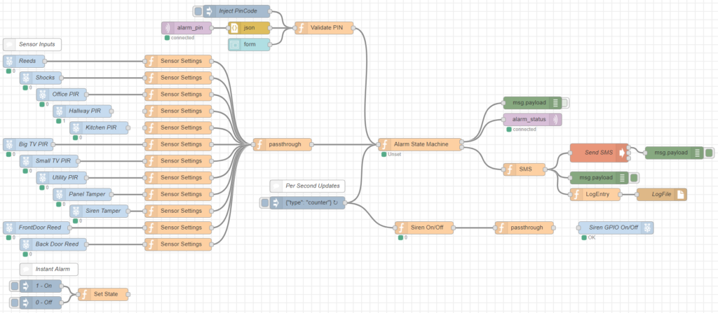
I’ll walk through the sections of the Note-Red nodes to give an overview of the functionality. I think it makes sense to start with the inputs.
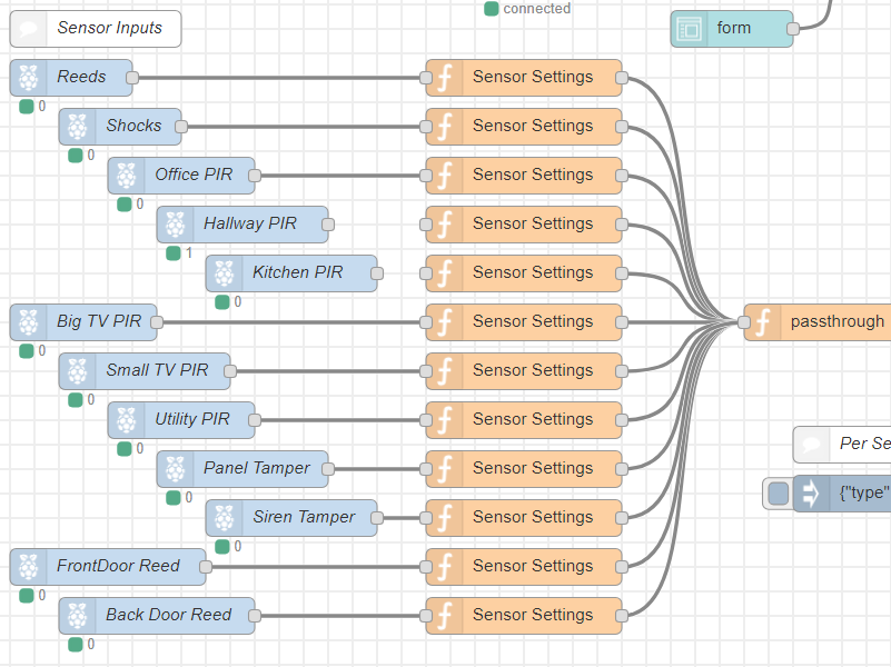
Here I use the Raspberry Pi wiring-pi node-red plugin, which allow me to drop a node onto the workspace for each GPIO pin I want to read. That gives me a 1 or 0 sepending on whether the incoming pin is high or low, ideas for reed sensors, shock sensors, PIRs, camera triggers, etc. Each GPIO is fed into a function which builds a JSON string for passing onto the core logic. The JSON string contains such things as sensor name, value, and delay on trigger (a door would have a delay to give time to key in the pin code), and delay on set (allowing a door to be open while the alarm in being set. THere’s also a setting for immediate alarm, such as where tamper switches are triggered, so it immediately alarms if someone opens the alarm panel, for example.
Next onto the core logic.
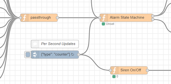
The core logic is basically a state machine with five states.
- Setting – Counting down the timer until set
- Set – waiting for trigger or PIN Input
- Unsetting – counting down the timer until unset
- Unset – Unarmed
- Alarm – Alarm triggered
So there’s rules for going from one state to the other depending on the input. If the alarm is “setting”, it’s counting down, and if there’s no other input, it will go to the “set” state after 30 seconds. If there’s a pin code entry, it will go back to unset. There’s rules similar to this for each state.
Next the outputs:
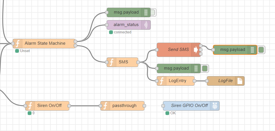
So the alarm system can generate multiple outputs, including sending a text message and enabling the sirens. The SMS function formats the string for the text message, including what happend, what sensors were triggered, etc. The Siren output is simpler, just on and off. All events are also logged in a log file, which is handy for historical info, was it set, etc.
There’s a couple more inputs, and they’re to handle the input of the pin code.
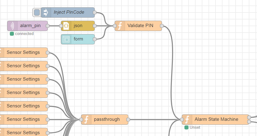
Here there’s three methods of input
- Direct PIN code injetion from Node-Red interface
- MQTT listner
- HTML Form
The PIN can be injected via the node-red interface by clicking on the top node. There’s also an MQTT listner waiting for MQTT packets from the Raspberry Pi running the keypad python script, and finally a web interface that allows the user to browse to the relevant page and enter the PIN code.
The hardware has changed since the last article, here’s a view of the current system. Note the USB keypad instead of the touchscreen.
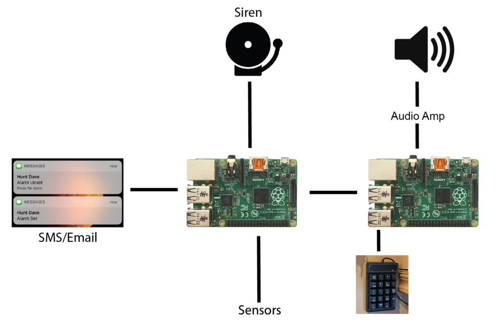
So now on to the keypad. This part of the system used to be a touchscreen interface on a Raspberry, but I’ve simplified that since. It’s now just a Raspberry Pi with a USB Numeric Keypad.
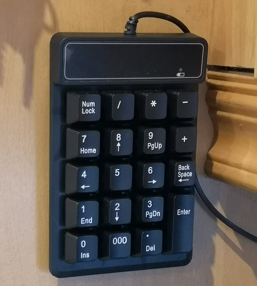
The keypad is a USB keybar from Amazon.co.uk, chosed for it’s nice compact form factor.
The python script that runs on the Raspberry Pi(s) with the keypad(s) has several functions.
- Reads the Keypad
- Opens an MQTT connection back to the Raspberry Pi running the Node Red software for teh core of the alarm system
- Plays WAV files out to audio amplifier and speaker, depending on the event
The keypad Pi has several wav files for the different events. WHen a key on the keypad is pressed, a “pip” sounds, for user feedback. When the alarm is setting, a beep sounds every send, then there’s the voice syntheis for “System Unset”, “Sensors Open”, etc. I feel it’s better feedback than looking at a touchscreen, and the feedback from the users is more positive.
The keypad, as described above, is only one of the ways that the PIN code can be entered, so if this is not functional, there’s still the web and node-red interface.
And finally, here’s a quick video of the keypad in operation.
Hello
Congratulations, great work!
Very interesting your project! I’m working to set up a central alarm system similar to yours!
I would like to know how you did with your reed sensors, they are directly connected to the GPIO, or is there any additional circuit with resistors etc?
Would you like to share this, or give me some information?
Thank you!
Hi Douglas,
I directly connected, there’s a pull-up resistors in the Pi that did the job nicely to give a clean on-off reading.
Regards,
Dave.