 I finally bit the bullet and uninstalled the Nest Thermostat that I got a couple of months ago. I was not happy with it’s ability to keep my house at a stable temperature. There was also the problem of the circulation pump feeding the heated water to the radiators (covered elsewhere on this blog).
Once I’d decided how the system was going to look, I set about building it. It was only afterwards that I drew up the following diagram. Click for full size.
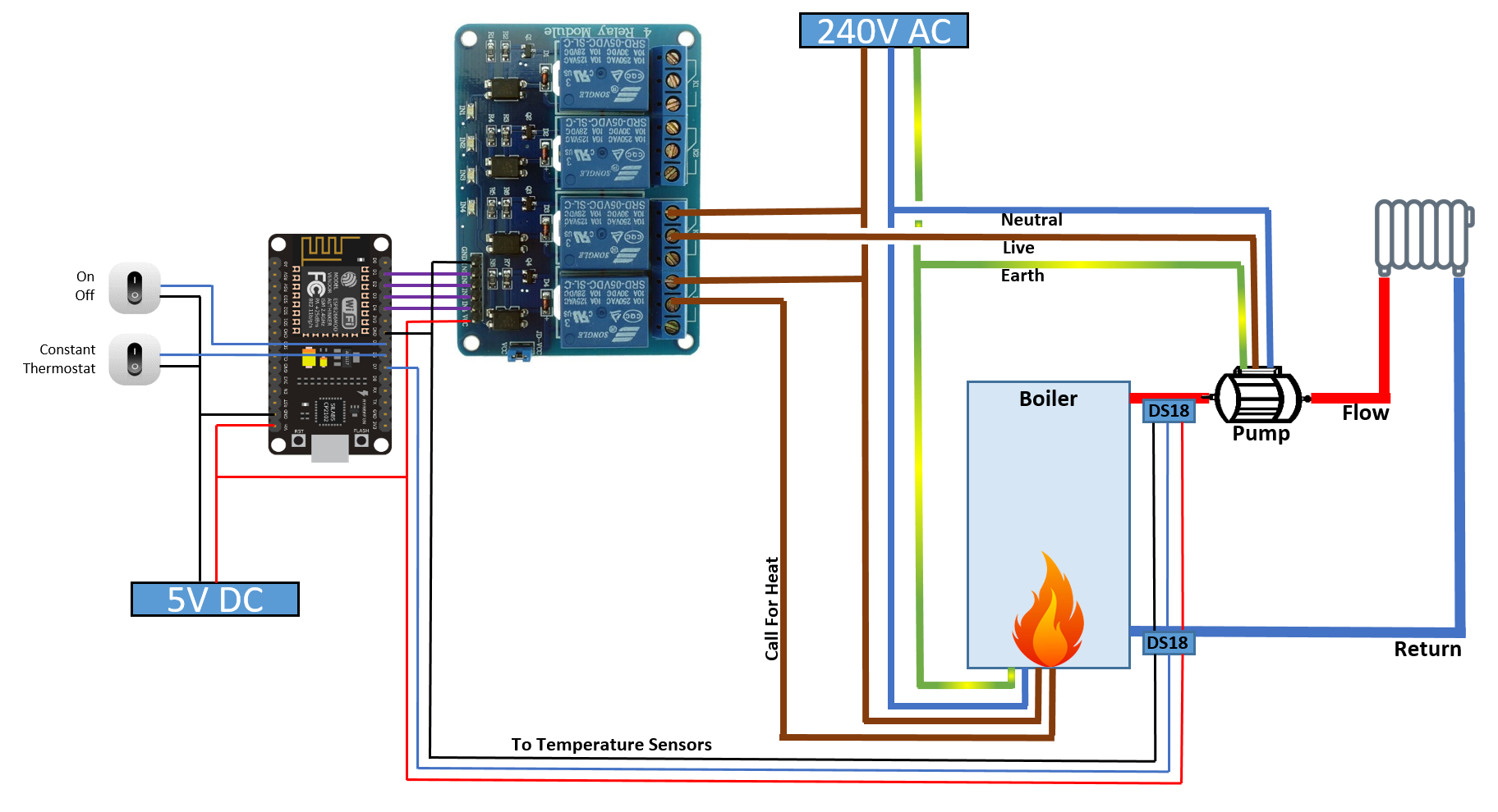
The two switch design was to facilitate the requirement in the house (from the family) that any “smart” device I build, it has to work the same as what went before, then the smart stuff can happen on top. For example, if I put in a smart light switch, then it has to work when you switch the switch. If the WiFi is down, it still must turn on/off the light. No excuses. So the MCU is programmed to do the basic functionality even if it can’t do the smart stuff. Same in the heating system design. The “constant” switch is there if the WiFi is down. When the switch is set to “constant”, the thermostat is ignored, and any incoming MQTT messages to switch on or off the burner are ignored. It works like the old system, when constant was on, heat was being delivered. The internal thermostat in the boiler will bring up the water to the required temperature, then cut the flame. The temperature of that water can still be adjusted with the knob on the front of the boiler. So the system can be used even if there’s no WiFi, or Kindle Fire tablet for thermostat control.
Then, when the switch is toggled to “thermostat”, the smart stuff happens, and the “request for heat” is driven by an algorithm based on the current temperature in the house compared to the desired temperature.
And of course, the system on/off switch specifies whether the heating is on at all. If it’s on, it uses either the constant or thermostat algorithms, if it’s off, the whole system is off. Nothing happens. 🙂
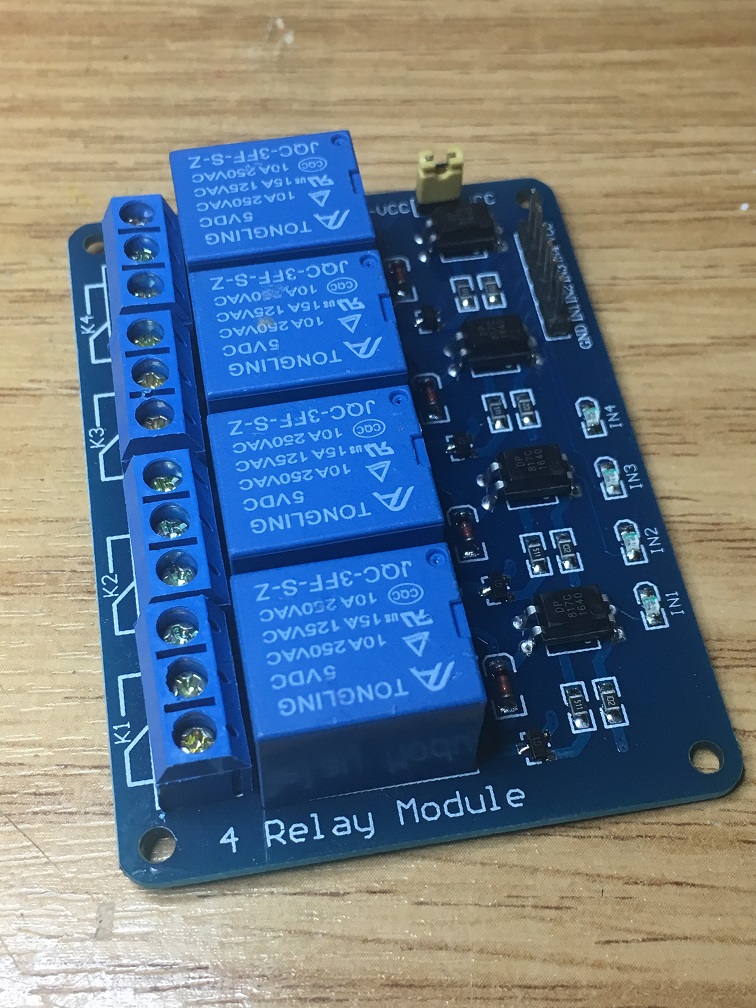
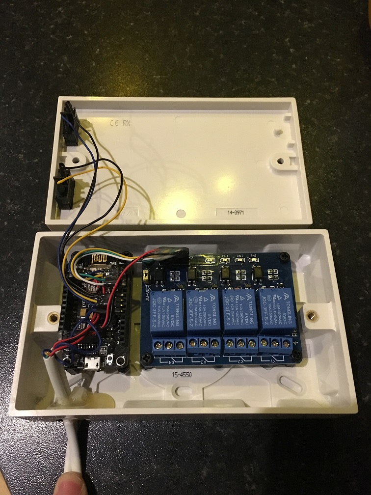
So my new design needed to switch more than one device independently, the burner itself, and also the circulation pump. So I needed a multi-relay setup. Luckily I had all the parts I needed lying around. I used a 4-way relay board, for future proofing 🙂
Also, I decided to use a NodeMCU board rather than the smaller WeMos D1 Mini, as it had plenty of GPIO’s to play with. I needed:
4 for the relays
2 for the switches
1 for the 2 x DS18b20 Temperature Sensors
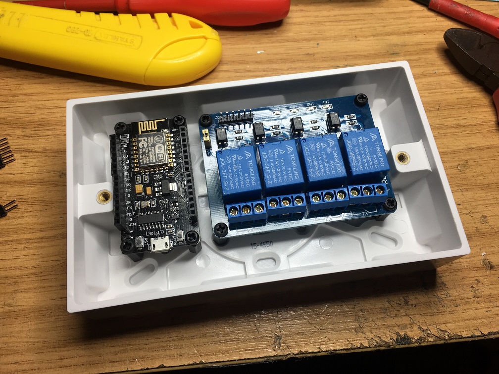
I’d have probably got away with a D1 mini, but there’s more GND pins available on the NodeMCU, making the wiring a bit easier. Then there was the issue of enclosure. Well, seeing as it was going to have 240Volts AC running through it, I thought I’d better use an electrical enclosure, so I got a blank 2 gang faceplate and box in my local hardware store. I dropped in the relay module and NodeMCU to test for size, and then added some 12mm standoffs to keep them in position.
I also found two nice switches, good positive feel to them, and nice quality. Ideal for the on/off and constant/auto switches. I mounted the switches on the side of the box where they’d be well away from the mains voltages, and fit nicely alongside the NodeMCU.
Here’s the box with all the GPIO’s wired up. A couple to the switches, four to the relay module, and one to the two DS18b20 temperature sensors for the hot water pipe out of the boiler.
The ends of the white multicore cable (alarm-6-way) are DS18B20 temperature sensors, which I’ll cable tie to the flow and return pipes on the boiler. They are small devices that look just like small transistors:
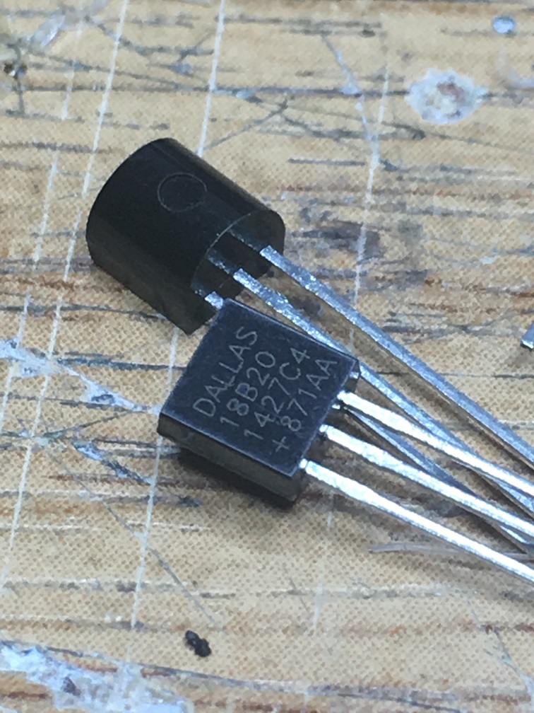
So I soldered them onto the other end of the cables coming out of the control box, with plenty of heat shrink, leaving the device itself exposed so I could apply plenty of thermal paste around it to give a more accurate reading from the water pipes. Here’s the installation of the temperature sensors, showing the heat shrinked cable and cable tie holding it into position, along with the thermal paste.

So once all the wiring was done on the DC side, over then to the AC side of things. The prep for this was to have the software ready for the NodeMCU, which handled the buttons, switched on the relays appropriately, and allowed me to re-flash the firmware over-the-air, as I didn’t want to have to be opening up the box if I wanted to make improvements to the software. The base for the software on the NodeMCU is the excellent Sonoff sketch by Theo Arends. I’ve modified it for us with NodeMCU and to fit the use case a bit better. E.g switching on and off the circulation pump based on the temperature difference between the flow and return pipes of the boiler. And it also has a web interface! 🙂
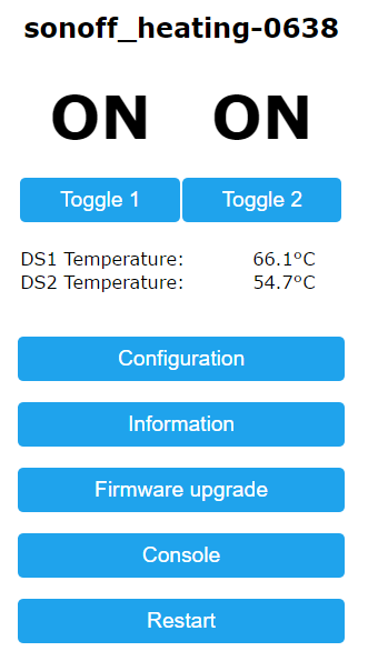
The web interface is rarely used to toggle the relays, as that’s left to the algorithms and thermostat software running elsewhere, but the main feature is to upload new software to it, which is as easy as browsing to a file locally and uploading it.
The algorithm for the circulation pump is something like this
if “request heat” is TRUE (that could be the constant switch, or the thermostat temp being below measured temp),
turn on the pump
else
if temp > 30
turn on the pump
if temp < 28
turn off the pump
This is one of the two main reasons I decommissioned the Nest Thermostat. The circulation pump was being switched off as soon as the burner was switched off. They were tied together. So the hot water remained near the boiler, and was circulated only when the burner was on. My plumber said that this was not ideal, and that it should stay on based difference between the flow and return pipe water temperature. Maybe the Nest could be wired to control the pump independently, but I preferred the option of being able to do it based on the flow/return pipe temperature difference.
Anyway, once I’d tested the software on the bench to make sure it was close enough to allow me to work the heating system (I didn’t want to freeze out the family), I started the job of wiring in the cables for the burner and the circulation pump.
So here’s a picture of the electrical wiring completed and powered on (in this setup when the led’s are on the relay is open)
You might notice in the above image that I’ve added a thick plastic seperator between the DC control part of the box and the mains voltage AC part of the box. For an extra bit of isolation.
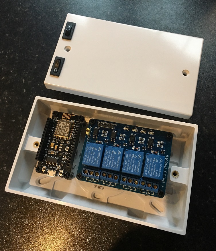
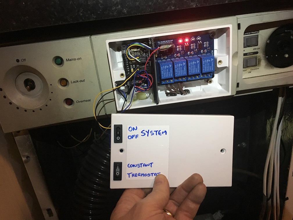
And the box closed, ready for use.
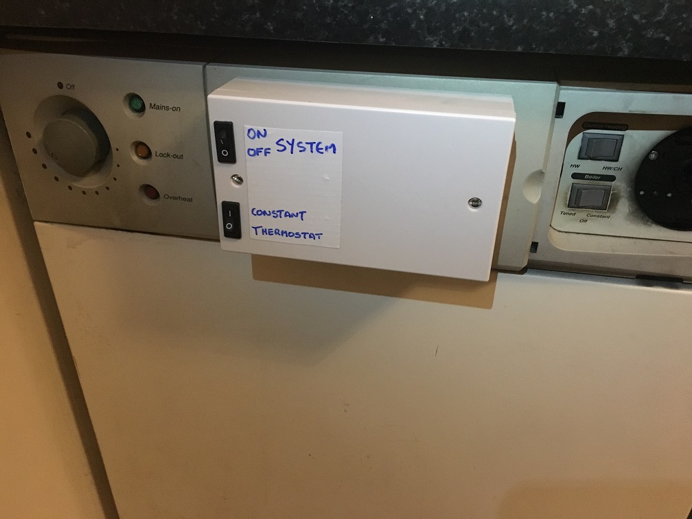
I just love the temporary label. 🙂
I plan on bring in another blank plate to the local FabLab and getting some nice letters laser etched onto it. I have to decide what they’ll be first, and maybe even put a big fancy logo with a system name or something. Feel free to suggest something in the comments below 🙂
I gave it a run for 24 hours, and tweaked the software as I went. It’s now quite stable, and as you can see from the graph below, it’s quite stable at the right hand side, with the latest software and temperature set to 19.5C.
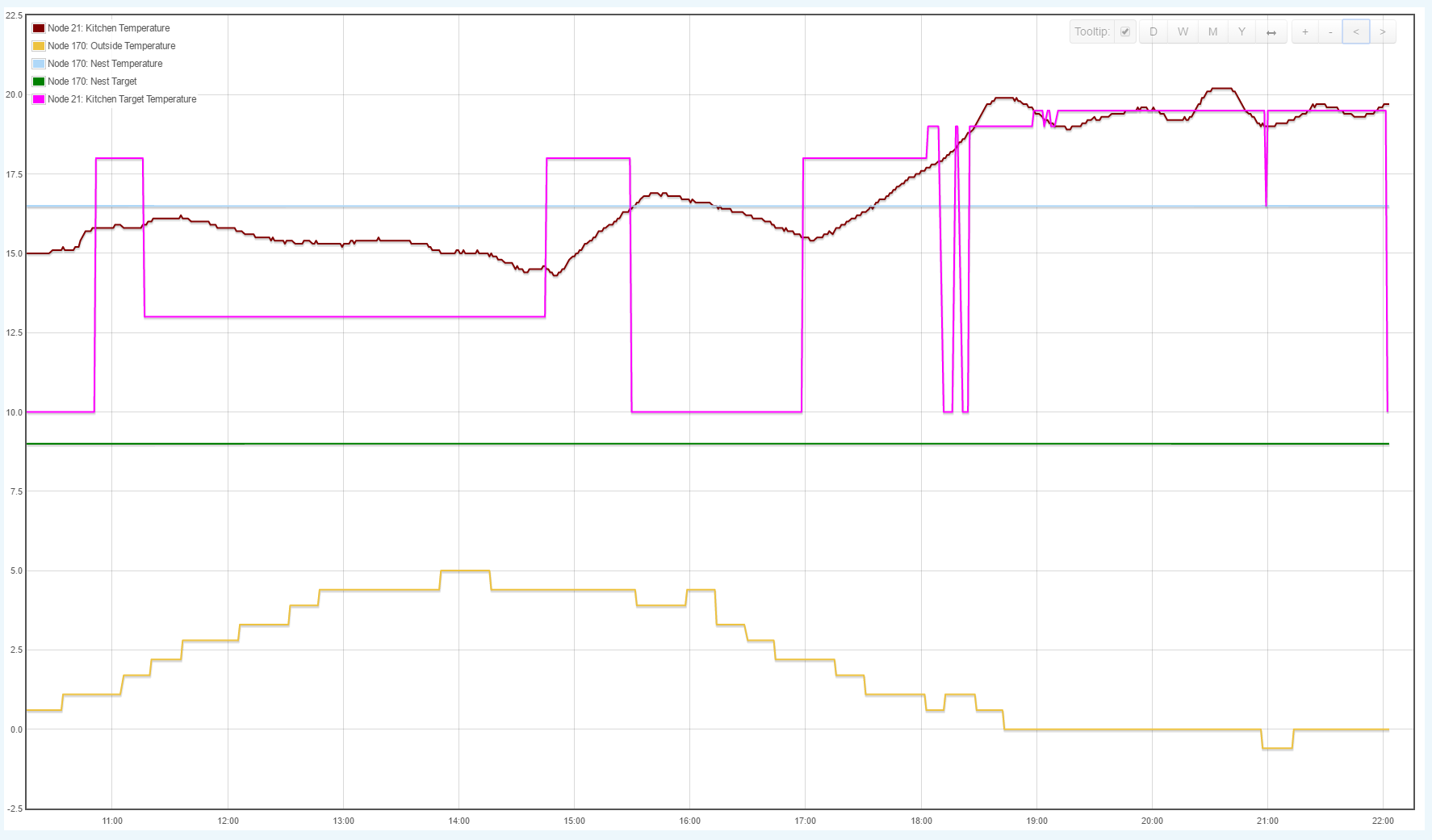
The Nest Thermostat really struggled to get that kind of consistency. And, I hope to improve the algorithm over the coming days to reduce the variance. It’s a very simple on/off when temp is below/above the setpoint.
At the other end of the system is a Kindle Fire HD6 tablet mounted on the wall in the kitchen, running Imperihome software. See here for an article on the mount I designed and 3D-printed, and the STL files are there as well for free download!
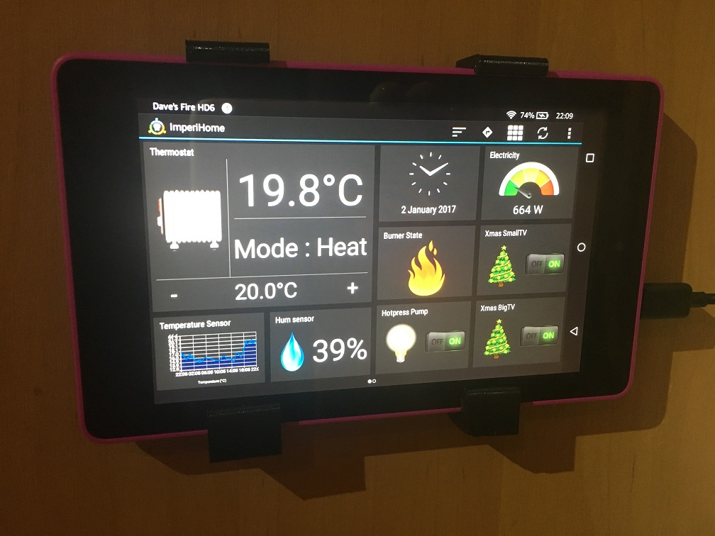
The thermostat widget is perfect for this system. You can set the temperature with the “+/-“, turn on and off the heat with “Mode”. Also, I’ve added a flame icon that shows when the system is requesting heat, just as some extra feedback that the system is working. The temperature sensor in the bottom left is what’s feeding into whether we need heat or not, and that’s coming from a device in the middle of the kitchen. I’ve got about a dozen temperature sensors around the house, I might do some kind of average in the future, it might be better than basing the requirement for heat on the temperature of one room, especially the kitchen, as that can get quite warm without heating, especially if there’s cooking going on.
One really nice feature of the Imperihome app is the camera can be configured to keep an eye out for movement, so if someone walks by or comes up to the tablet, the dashboard will appear. Very handy, one of the best features of the software. One downside about the tablet is that it’s from Amazon, and the Google Play store is not on it by default, so I had to load that on first before I could purchase Imperihome.
Oh, and there’s one more part of the system that’s worth mentioning, and that’s Node-Red, which is really the brains of it all. The tablet is the input/output, as is the burner, circulation pump and flow pipe temperature sensors, but Node-Red decides how it all hangs together. Node-Red, plus all the other stuff for my home monitoring is running on an Up-Board, a small, single board computer from Aaeon.
Here’s a pic of some of the flow’s I’ve currently got running in my system.
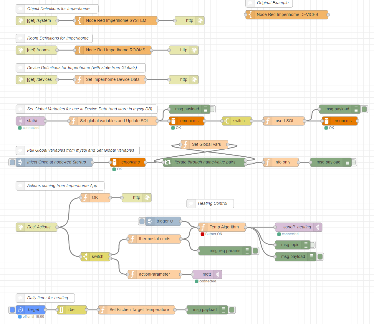
Also in there is a timer-switch node (bottom flow), which has a schedule of times for on/off. This node will send a change in state a certain times in the day, and it has preset temperatures. So during the night, the temperature is set low (16.5 degrees), and in the evening it’s set to 19.0 degrees. Of course, as soon as someone tweaks the temperature using the thermostat widget, that takes priority. I plan on adding more sophisticated timing in the near future, but it’s fine for the short term.
Bear in mind that there’s a lot more going on there than just the heating system, it’s also handling the Imperihome controls for the Christmas Lights, domestic water pressure pump, office lights, etc. But it’s a great way of hooking a bunch of IOT devices together, and it’s easy to see what’s going on (as long as you lay it out in a sensible way). I can see why Node-Red is described on it’s website as “A visual tool for wiring the Internet of Things“. I also picked up a lot of useful bits and pieces from Pete Scargill’s Tech Blog, which is packed full of useful information about gadgets, IOT, etc.
Only time will tell whether it was worth the effort, but with the stability of the temperature in the house after only 24 hours, I can see a (positive) difference already.
Nice work Dave, how about “Burning Sensation Heating Systems”, alternatively “Burn It To Create Heat” Industries…..it’s a slow day at work…..
I like it John. How about this?
http://www.davidhunt.ie/wp-content/uploads/2017/01/Burning.png
🙂
wow cool …! (tho, not literally!)
can I ask what os you are running on the up board and would a Pi3 do the job as well?
Michael, I’m running Ubuntu. Any decent single board computer should be able to handle Node-Red, including the Pi3. 🙂