Recently I started a project using ws2811 RGB Pixel drivers, and wanted to write some software on a Raspberry Pi, ESP8266 or ESP32 that bit-banged the GPIO ports to generate the data stream suitable to drive the pixels.
I looked on Amazon.co.uk, and found the following: “KKmoon LHT00SU1 Virtual Oscilloscope Multifunctional Full-Featured Signal Generator, 8 Channels,16Msps, 3MHz” for £26.99. That seemed reasonable value, so I ordered it.
A couple of days later, it arrived. I had already written the software to generate the pixel data, and was having some success, but being able to see what was coming out of the Logic Analyser was way better, I could see the frequency of the data, the shape of the waveform, etc.
Setting it up was easy, I was using the free pulseview software, which is available from Windows and Linux. Installing the Windows version was a breeze, the only tricky but was using Zadig to install the WinUSB driver for the “Unknown Device #1” that appeared in my device manager when the Logic Analyser was attached.
One the correct driver was installed starting up Pulseview was easy, detected the device straight away.
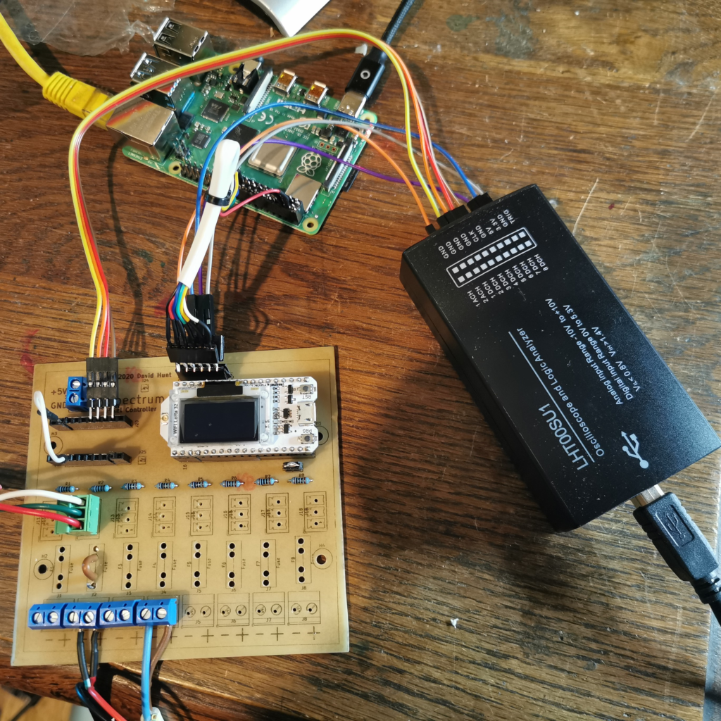
So in the picture above we have a Raspberry Pi feeding data over SPI to an ESP32 microcontroller, which in turn bit-bangs it’s GPIO outputs to form pixel data for up to 8 strings of RGB LEDS. We can see the analyser hooked up to the SPI bus on the Raspberry Pi coming to the ESP32, and at the same time, 4 of the pixel outputs from the ESP32.
So here’s the PulseView display for that setup:
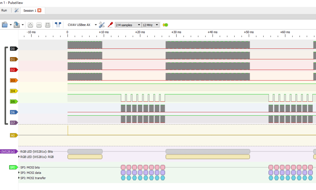
There’s a lot going on, but lets take it in sections. THe top 4 pins are the 4 connections to the GPIO outpus on the ESP32, with the LED data. D4 is not connected, so the next three are connected to the SPI bus between the Pi and the ESP32. The first os the Chip Select, and then clock and then MOSI (Master Out Slave In). I’m not looking at the MISO (Master In Slave Out), as there’s no data going the other direction.
Then there’s the bottom two sections which is the decoded data. It knows how to decode a variety of signals, including SPI and ws2811 RGB LED data, which is fantastic for this project, as I’m having to code the ESP32 to get the precise timing needed to driver the LEDs properly, and I couldn’t have done it without a logic analyser.
One downside is the max frequency of the analyser. I found it to be relatively stable at 12 million samples per second, which is not great for trying to look at an 8MHz SPI data rate. In fact, it’s useless. Only 1.5 samples per Hz on the SPI bus. I’d need maybe 10 times that, say, 80 ms/s (million samples per second), so I get 10 divisions for each cycle on the SPI bus, which would be ideal. Anyway, you get what you pay for, and 12 ms/s is grand for the 800kHz data for the RGB Leds.
When I was writing the SPI transfer functions, I dropped down the data rate to 1MHz, so I was able to decode it with the analyser, but once I started driving the LEDs, the refresh rate was too slow sending over SPI at 1MHz, so I bumped it up to the fastest that the ESP32 can handle in slave mode, which is max 10MHz, and the Pi can go 8 or 16, so 8MHz it is.
Then to the RGB data. The Pulseview software decodes very nicely. If I zoom in on the data above using Pulseview:
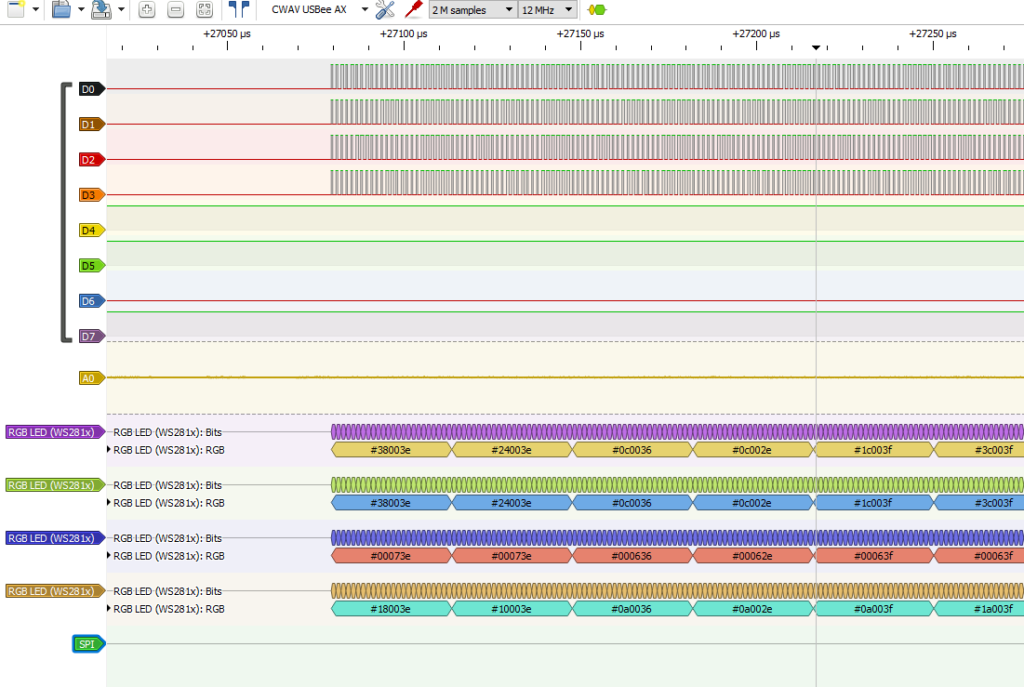
Using this, I can verify the data coming from the Pi through the ESP32 and out to the pixels. The analyser was a great help when I was not getting the colours I expected.
Zooming in further, we can see the waveform going out to the LEDS:
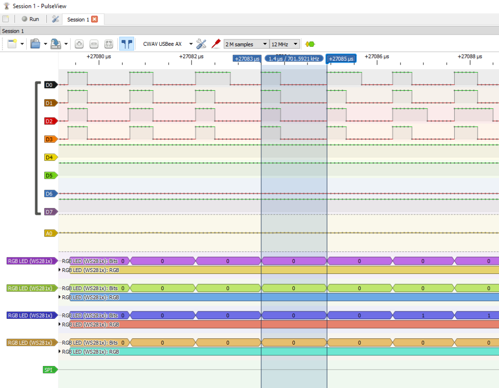
By moving the cursors (blue markers) to the rising edge of the pulse we can see the frequency and duration of each bit of data. This is showing 1.4uS at 700kHz, but ideally it should be 1.25uS at 800kHz. A bit more work to be done there. The data displays fine, but with 680 LEDs worth of data going out on each of the 8 outputs, the faster I can get it out, the faster the refresh rate.
Also, I need to have the SPI data all received, then disable the FreeRTOS operating systems scheduler so that the RGB data stream does not get interrupted while the data is being sent out, otherwise we’ll get corrupt colours and flashing on the LEDs.
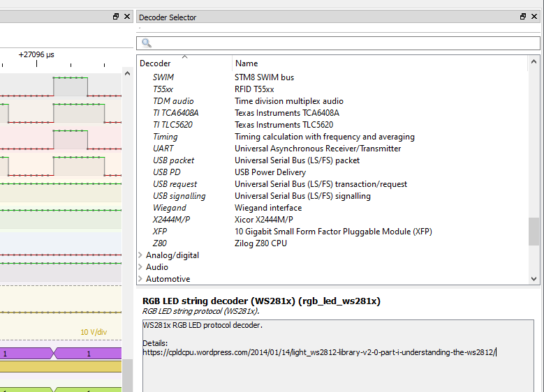
There’s a huge selection of built in decoders if you’re doing any other kind of work that needs digital signal analysis (up to ~1MHz to be honest)/
That’s about it from me, I thought it was a useful enough tool to write a quick blog about. I got it from Amazon.co.uk and it cost £20.99. Fantastic value for what it allowed me to do.