 Here’s another in the series of articles of photographic uses for the Raspberry Pi SBC (Single Board Computer). This time, it’s re-purposing an old flatbed scanner as a macro rail for focus stacking images in macro photography.
The Plan
There’s a common issue with shooting macro photography, and that’s the limitation in depth of field (or depth of focus). It can be as little as 0.5mm, depending on the camera settings and magnification you’re trying to achieve. A solution to this is to take several images, each one moving closer to the subject by a tiny amount. Each image will have a different part of the subject in focus. You can then combine all the sharp parts of the images together using some free software called CombineZM, and end up with a completely sharp image from front to back of the subject. The difficulty with this is moving the camera accurately at such small distances. Once solution is to turn the zoom ring on your lens slightly, but that’s still hit-and-miss on highly magnified images (1:1 and smaller). Commercial solutions can cost as much as $600, including controller.
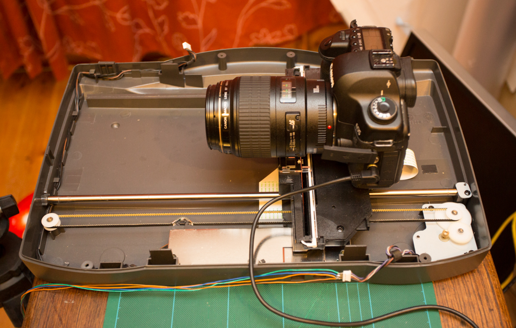
So, I came up with the idea of re-purposing an old flat-bed scanner that I had in the attic gathering dust. It’s so old, that the most recent drivers available for it are for Windows XP. So it hasn’t been used in a couple of years. Being a scanner capable of 2400 dpi, it was definitely accurate enough, but would it be able to move a 3KG camera and lens? If I could get at the stepper motor to drive the scan element, maybe I could attach a camera to it and move it in very fine increments, ideal for macro photography.
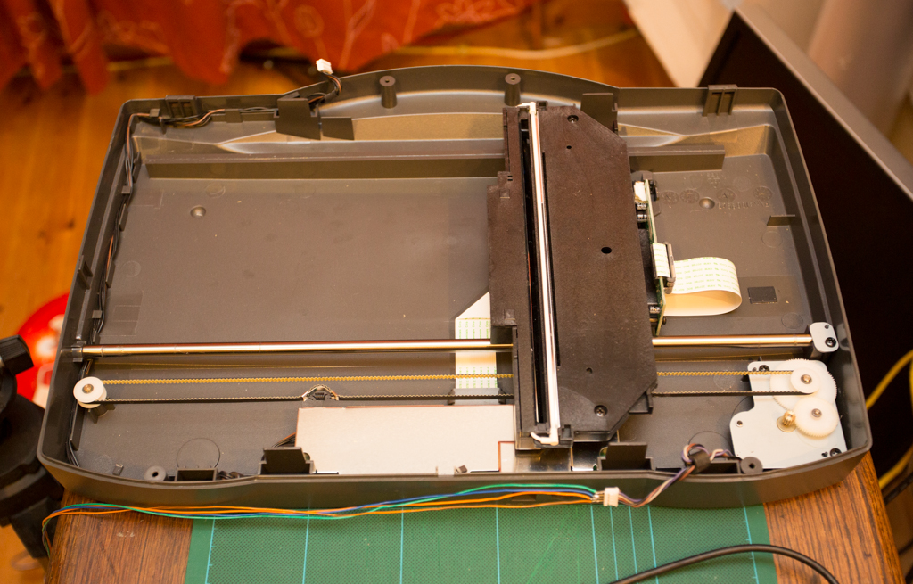
Once I took the cover and the glass off, I was left with a nice flat platform on which to place my camera, and a 4-wire connection to the stepper motor to drive the platform forward and back. The stepper motor drive can be seen in the above image in the bottom right.
Mounting the camera is simply a case of placing it on the platform. The drive is slow enough that it does not dislodge the camera while it moves. The camera shown is a Canon EOS 5D Mark II, but it should work with Nikon, Sony, etc. Any camera with a shutter release mechanism.
The Circuits
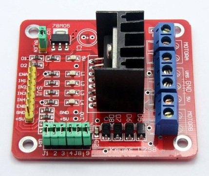
This project was made much easier by using an off-the-shelf stepper motor drive unit (see pic). It’s a dual H-Bridge motor drive unit. I had it off eBay for €9. It has the capability to drive 2 DC motors, OR 1 stepper motor with 2 coils. In this project, we’re driving one stepper motor with two coils.
So, connecting in the 4-wire stepper motor interface into the MOTORA and MOTORB connections, and adding in a PSU in the form of 3 x AA batteries to drive the motor, I then connected 4 GPIO outputs of the Raspberry Pi directly onto the 4 inputs to the stepper motor driver board. I wired the EnableA and EnableB pins to the +5V, as I want both coils in the motor to be enabled, and saved myself a few GPIO pins in the process.
The sequence I’m using to drive forward is 1000, 0100, 0010, 0001 (repeating), and backwards, is 0001, 0010, 0100, 1000 (repeating). You can see in the sequence that it’s enabling one of the coils on the motor at a time, causing it to rotate.
With a small bit of code, I was then able to drive the platform in the scanner forward and backwards ad various speeds, depending on how fast I ran the sequence to the motor (see below for the code)
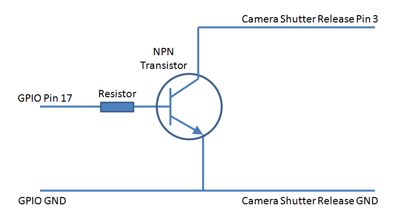
The next step was to drive the shutter of the camera between each move of the platform. This was done using the following circuit.
So, now I can move the camera towards the subject in increments as little as 0.02 mm, taking an image each increment. That’s incredible resolution for something this easy to build!
The Code
Here’e a snippet of python code to move the motor a number of steps, and trigger the shutter. Run this script for each frame in your stack. I guess you could stick a loop around it if you know how many frames you want to take, but I wanted to keep it simple for this article.
import sys
import wiringpi
from time import sleep

# Parameters:
#     direction (0 or 1)
#     number of steps (int)
#     delay between steps (float)

gpio = wiringpi.GPIO(wiringpi.GPIO.WPI_MODE_GPIO)

motor_pin_a = 0
motor_pin_b = 1
motor_pin_c = 4
motor_pin_d = 14
shutterpin = 17

gpio.pinMode(motor_pin_a,gpio.OUTPUT)
gpio.pinMode(motor_pin_b,gpio.OUTPUT)
gpio.pinMode(motor_pin_c,gpio.OUTPUT)
gpio.pinMode(motor_pin_d,gpio.OUTPUT)
gpio.pinMode(shutterpin,gpio.OUTPUT)

wiringpi.pinMode(shutterpin,1)
wiringpi.pinMode(motor_pin_a,1)
wiringpi.pinMode(motor_pin_b,1)
wiringpi.pinMode(motor_pin_c,1)
wiringpi.pinMode(motor_pin_d,1)

if sys.argv[1] == '1':
	start=0
	finish=int(sys.argv[2],base=10)
	increment=1
else:
	start=int(sys.argv[2],base=10)
	finish=0
	increment=-1

stepdelay=float(sys.argv[3])
a = [ '1000', '0100', '0010', '0001']

for j in range(start,finish,increment):
	i = j%4
	if a[i][0:1] == '1':
		gpio.digitalWrite(motor_pin_a,gpio.HIGH)
	else:
		gpio.digitalWrite(motor_pin_a,gpio.LOW)
	if a[i][1:2] == '1':
		gpio.digitalWrite(motor_pin_b,gpio.HIGH)
	else:
		gpio.digitalWrite(motor_pin_b,gpio.LOW)
	if a[i][2:3] == '1':
		gpio.digitalWrite(motor_pin_c,gpio.HIGH)
	else:
		gpio.digitalWrite(motor_pin_c,gpio.LOW)
	if a[i][3:4] == '1':
		gpio.digitalWrite(motor_pin_d,gpio.HIGH)
	else:
		gpio.digitalWrite(motor_pin_d,gpio.LOW)
	sleep(stepdelay)

# sleep 100ms to let things settle.
sleep(0.1)

# Trigger the camera shutter.
gpio.digitalWrite(shutterpin,gpio.HIGH)
sleep(0.1)
gpio.digitalWrite(shutterpin,gpio.LOW)
The Results
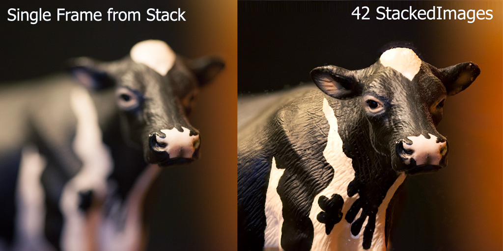
Here’s a video of the rig in operation, including a video of 42 stacked images played at 6 frames per second. This shows how the point of focus changes as the camera moves towards the subject
[embedplusvideo height=”253″ width=”450″ standard=”http://www.youtube.com/v/1eMzD0t0Lrg?fs=1″ vars=”ytid=1eMzD0t0Lrg&width=450&height=253&start=&stop=&rs=w&hd=0&autoplay=0&react=1&chapters=¬es=” id=”ep4950″ /]
Here’s a few sample images taken using the flatbed scanner rig (MacroPi) 🙂
Next Steps
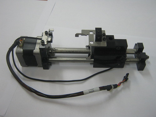
For a more robust solution, I’ve ordered the following part. Functionally it is the same as the flatbed scanner, but should allow me to more easily mount on a tripod for portable motorized focus stacking.
It was everything I was looking for all in one unit. A motor, rails, leadscrew, linear motion platform, all in one unit, all pre-assembled for about €83. I’d already got a 4-wire stepper motor working with the Raspberry Pi a few weeks ago, so the software was ready to go, it just needed me to build a macro rail. This thing would save me a load of time, and I’d end up with an industrial quality solution.
Some of the specs:
Motion length – 11.4 cm / 4.5″ ~
Leadscrew length – 14 cm / 5.5″ ~
Rail step (pitch) – 16 TPI
1.8° Step Motor – Made by SANYO DENKI
Type: 103H548-0498
Step: 1.8/step
The motor has 200 steps per rev, so with 16 turns per inch, (6.3 turns per centimetre), that gives me a movement of 126 steps per mm. Plenty accurate for what I need.
Raspberry Pi is a trademark of the Raspberry Pi Foundation
About the Author:
By day I’m a senior embedded Linux software engineer. In my spare time, I take pictures, and play with gadgets and technology.
Twitter: https://twitter.com/climberhunt @climberhunt
Facebook: https://www.facebook.com/davidhuntphotography
Nice project. I can see myself using this as a starting point to build a motorised “barn-door” mount for long exposure astrophotography. I guess it could also be adapted to become an automatic dolly for time lapse with motion or panoramic shots. The possibilities are endless! Just a thought on the focus stacking though – could you not just do it using libgphoto and a USB connection to the camera?
Yes, USB is an option, and only one line of code change, also saves you building the circuit for the shutter port. Cool!
Where can I buy the hardware in your last picture?
Interesting, I’ve had 4 emails in the last hour about that! 🙂
http://www.ebay.ie/itm/280743516102#ht_2635wt_1165
6 left Get ’em quick, they won’t last long! 🙂
Dave.
1 less now. I just bit the bullet and ordered one. Looks good and going to enjoy tinkering away to get this working!
Only 1 left! 🙂
Hi Dave,
Thanks for your tutorials! I just purchased one myself and am in the process of buying the parts to go with it. Do you know if yours is a unipolar or bipolar stepper motor?
Thanks and look forward to the updates.
Rick
Rick, I believe it’s a bipolar motor.
Dave.
Hi David,
Just wondering if you have incorporated you new stepper/rail system yet? I just received mine but still unsure of what I am doing… From the wires at the motor it looks like a unipolar; but the connector is only four wires, which would lead me to believe that it is a bipolar.?.?. Also what voltage are you driving the motor at? My stepper drive is at 5v but some of the data sheets call the 103h548 motors at 3.6v. Anyways, look forward to building one soon and following your progress!
Thanks,
Rick
Rick, I haven’t taken it ay further, but I did connect it up to the driver and it worked fine. I was using 3 x AA NiMh batteries, so that would have been about 3.6 volts. Dave.
Hi David, another great idea!
I assume it would be easy to add in a couple of lines of code so that you could add another step by an input on the pi, or even put in the number of steps you want at the beginning? i think I could do it in basic, but I am new to python.
I would recommend a Opto-isolator over a transistor to use with the camera shutter. Would be sad to fry the expensive 5D D:
I tested it with an arduino, the delay isn’t that big of an issue (my sony DSLR has quiet some delay over the external shutter release port… tried some stuff with wirelles flashes and wirelles shooting at the same time)
How did you make the camera shutter release? It looks like you bought a shutter release cable and cut apart one end for connection to the NPN transistor? Is the resistor intended to drop the voltage going to the camera?
Bob, Yes, I had an old shutter release in which the switch was broken. I never throw anything out! 😉
That’s an excellent project and great set of instructions. Have you used ImageJ? It’s open-source image analysis software (funded by the NIH) and it’s scriptable.
Dustin, I’ll take a look. Thanks! Dave.
Is there a way to waterproof this for damp or outdoor conditions? Thanks, Bob
Bob, I’d only intend on using this indoors. No wind to move subjects around between shots! 🙂
However, with the Linear Motion rail, it should be relatively damp-proof. I’d be more worried about the Raspberry Pi, to be honest…
Dave.
I have zero experience with stepper motors, so this should be a good first project. I found my retired flatbed scanner and removed the glass top. The motor is a Neocene 2T3543 PM-type stepper marked as being 4 Ohms. It is 12v and has 4 wires. I guess I will need to supply it with 12v. From watching your video repeatedly, it looks like your camera is sitting on the scanner platform unsecured. Or did you modify the platform to secure the camera?
Bob, 3v – 4.5 v should be fine. And yes, the camera is just sitting on the platform. The speed is slow enough so as not to dislodge the camera.
That’s how I made focus stacking assistant. The thing is small and portable, I use it all the time to shoot pictures for the site.
http://www.circuitsathome.com/camera-control/focus-stacking-assistant-for-eos-cameras
Try Zerene Stacker. It’s a lot more versatile, and a lot simpler.
http://zerenesystems.com/cms/stacker
It’s probably worth mentioning that Zerene Stacker is a commercial application, prices range from $39 for the student edition to $289 for the full version.
I’ve ordered the stepper motor controller (about 3-5 weeks from China) and I’ll look around for a shutter release cable. I’m going to play with ImageJ since I’m on the Mac. Perhaps I can use this beginning experience to work more with insect photograohy. I will think of how to accomplish the same thing for photographing insects. It is difficult to set up a tripod with the camera pointed at a spider or mantis and then focus the lens such that the lens doesn’t drop slightly or the creature doesn’t scoot off and hide in fear. Part of my problem is the tripod I’m using has trouble locking a heavy camera exactly into position when it is on an extension rail. The weight of the extension rail and he angle it is pointed at makes the tripod tip over easily. A better tripod plus he linear motion rail might help with that because it can move the camera lens closer to the insect…hopefully without frightening it.
Why not use the Magic Lantern in your camera and let this kind of project for Nikon users.
Magic Lantern would work in most circumstances, but not if you are using extension tubes or reversing rings where you have no automatic control over the focus. Besides, it’s more fun connecting your camera to an old scanner! 😉
Does anyone know what Lytro is?
I think they do the same than this.
FYI: quite a few of those stepper motors support ‘half steps’.
fi: You mention as the forward stepping control sequence:
1000, 0100, 0010, 0001
You might want to see what happens with:
1000, 1100, 0100, 0110,
0010, 0011, 0001, 1001
Not that you seem to need it ‘here’, but with the same electronics, you can get the double ‘resolution’.
Possibly a silly idea: there is already an ST L6219 stepper motor driver on my scanner’s circuit board. It’s an SO24 surface mount package. Would it be practical to drive the stepper motor by soldering wires to the L6219 pins and connecting them to the Raspberry? Of course, it is very difficult to say without the schematic diagram and the manufacturer, if still in business, may be unlikely to give it to me. It is probably better to wait for my dedicated board to arrive from China.
Bob, probably a fine idea if the scanner is broken, but if it still works, you can always put it back together when you’re done with your macro shots. 🙂
Dave.
Dave,
Really enjoyed reading about your projects and in fact cited them on my blog here: http://www.hackthings.com/raspberry-pi-nearly-a-million-units-sold-but-is-yours-idle/
Very impressive work all around.
thanks,
Joe
wouldn’t it be easier just to attach a stepper motor to the manual focus dial? turn a bit, take picture, turn a bit, take picture and so on.. My thought is this way the camera does not get closer. Moving camera closer would make the subject a bit bigger each time the focus is adjusted to a deeper field.. Just my thought, I could be wrong though..
Cool project
Good idea. However, the engineering to build a jig to attach to the lens could be quite complicated. Might be worth it for the zoom, though! 🙂
Faced with another 2-3 weeks wait for the motor driver I ordered to arrive here from China, I ordered a “Big Easy” motor driver from Sparkfun Electronics which I should have by the end of this week. I have all the remaining parts needed except a breadboard. I could try to use the L6219 motor driver that is on my scanner’s circuit board, too. That may activate the scanning hardware itself, though. Better try to run the motor all by itself.
Dave, in your code you assign 0 to motor_pin_a. Pin 0 is actually a WiringPi pin name and it maps to BCM pin 17, also known as GPIO17, which in turn in is pin 11 on the Raspberry Pi Model B header P1. So your motor control wires are in P1 header pins 11, 12, 16, and 23 respectively and the camera shutter pin 17 is mapped to BCM pin 28 which in turn maps to the auxiliary header pin 3. Is this correct? Did you have any special reason for these pin choices? Putting the camera shutter pin on the auxiilary header is especially interesting. Thanks, Bob
Bob, I’m using the WPI_MODE_GPIO, and all the pins I’m using are within the first 8 pins of the GPIO header beside 3.3 and 5V supplies. Pin 3 – GPIO 0, Pin 5 = GPIO 1, Pin 7 is GPIO 4 and Pin 8 is GPIO 14. I’m doing that because I’m using an 8-way header connector I recycled from an old USB panel mount for a PC.
Hi Dave, thanks for letting me know. I’m still a little confused here. Is your “wiringpi” from this source –> https://projects.drogon.net/raspberry-pi/wiringpi/ ?
The motor driver I ordered from China arrived today, so I have the choice of using either that (it is the “HEX” brand and looks almost the same as yours, with the same L298 chip) or the Big Easy Driver from Brian Schmalz and Sparkfun Electronics. I’m going to use the Big Easy first, because the physical form factor is a lot smaller than the HEX L298, and it looks like the programming required is simpler too. I just need a few more parts: 3.5mm screw terminals, which should arrive Thursday or Friday. I’ll let you know what happens.
https://github.com/WiringPi/WiringPi-Python
Dave I am in the process of getting all the bits to do this, and think I get most of it. The bit that is confusing me is the enable A and enable B pins. Do you mean they are both wired to the 5v pin on the GPIO interface, or to the 5 V pin on the stepper motor driver? Also, does the battery pack connect in via the 3 terminals between motor A and motor B?
thanks
Steve, I connected both Enable pins to the +5 on the 8-pin header. And yes, the 3.6v from the battery goes to 2 of the 3 terminals between A and B.
Rgds,
Dave.
I’m trying to do the same thing – though as the basis for a timelapse slider.
I’ve got the stepper out of the scanner, and also got the same board as yourself.
I think I have the 8 pin wiring correct, but the wiring to the stepper motor is eluding me.
I have 6 wires, and i’ve identified the two sets of three wires so: two are the coil ends and one is the centre tap. It’s how these are wired to the motor end of the board. I’m assuming that the two coil wires go to the two terminals of motor A connection? Then where does the centre tap go? Does it go to GND, or to Vms? Or is it disconnected – a bit more googling leads me to believe this is the case.
Gareth, You should have 4 wires out of the stepper motor back to the controller, two on MotorA and two on MotorB. Only 4 wires to the stepper. Then Separately, take your battery into the +Vcc and Gnd (3.6v approx).
Thanks – yes, that’s what I’ve got now – I finally worked it out. The centre taps have to go to ground as well.
The other thing I ‘discovered’, having spent some time working out which wire went to which coil, was the sequence in which I needed to energise the coil wires was the same as the order they were in the connector.
Where can I obtain the threepin plug neded to connece to my EOS canon Camera please
NO HAY FORMA QUE FUERA TRADUCIDO A EPAÑOL GRACIAS
Hola Vicente.
Te recomendaría que tradujeras el texto usando Google Translator (translate.google.com).
Gracias.
Dave.
Hey David,
great Work & thanks for sharing this!
I think I will try to combine this article with your timelaps dolly. With an step-motor it should be fine to drive the slider back to his starting point – after it did his job. The normal DC-Motor isn’t so accurate or?
Is it right that i could use the H-Bridge motor drive unit also with 12V from an external Powersupply?
And: Is it possible to share more Pics or the Layout from the wiring diagram? I’m not the best electrician :).
That would be awsome!