
 Here’s how to build a Water Drop kit using a Raspberry Pi as a controller for a solenoid valve and camera trigger.
The Plan
(Standard disclaimer applies, batteries are a fire hazard, wiring them up incorrectly can cause a fire, burning, etc., not to mention possible damage to equipment. Do so at your own risk, etc).
First, you’ll need to get yourself a solenoid valve. There’s loads of these on ebay for about €15.
+hUTUg~~60_12")
We only need two GPIO pins, one for driving the solenoid valve, and the other for triggering the shutter of the camera. I used pins 17 and 18.
Since the solenoid is 12V, used a battery pack that takes 8 AA batteries, giving me about 11 volts, which works fine, and it’s more portable than needing an AC power supply. See my previous posts for a portable 5V power solution for the Raspberry Pi.
The Circuits
There’s a couple of (very) simple circuits to build, one for the solenoid, and one for the shutter release of the camera. In both cases, a 1K resistor should be fine.
First, the solenoid (revised after feedback to move the solenoid) (revised again to add the flywheel diode to protect the transistor against the inductive spike from the solenoid):

Next, the Shutter Release circuit:

The Code
This consists of a small bit of python. Run this each time you want to shoot two droplets and take a picture. The timings are suitable for when the solenoid valve is about 40cm above the surface of the water. Each drop is 100ms apart, just enough time for the first one to bounce back up and the second one to collide. You will need to adjust the timings for your own solenoid, camera, distance, etc.
import wiringpi
from time import sleep
gpio = wiringpi.GPIO(wiringpi.GPIO.WPI_MODE_GPIO)
shutterpin = 17
solenoidpin = 18
gpio.pinMode(shutterpin,gpio.OUTPUT)
gpio.pinMode(solenoidpin,gpio.OUTPUT)
wiringpi.pinMode(shutterpin,1)
wiringpi.pinMode(solenoidpin,1)

gpio.digitalWrite(solenoidpin,gpio.HIGH)
sleep(0.06)
gpio.digitalWrite(solenoidpin,gpio.LOW)

sleep(0.1)

gpio.digitalWrite(solenoidpin,gpio.HIGH)
sleep(0.05)
gpio.digitalWrite(solenoidpin,gpio.LOW)

sleep(0.12)
gpio.digitalWrite(shutterpin,gpio.HIGH)
sleep(0.1)
gpio.digitalWrite(shutterpin,gpio.LOW)
The Results
Here’s a few images using the solenoid above driven from the Raspberry Pi.
Here’s a series of just water:

And here’s another using milk into a pool of water with a bit of red dye ink:
–edit–
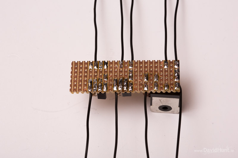
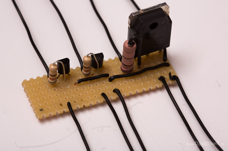
Here’s a pic of the solenoid with water container.

I’ve had lots of requests for pictures of the circuit, so here it is. The bigger transistor and resistor os for the solenoids and one of the smaller transistors is for the shutter release.

Raspberry Pi is a trademark of the Raspberry Pi Foundation
About the Author:
By day I’m a senior embedded Linux software engineer. In my spare time, I take pictures, and play with gadgets and technology.
Twitter: https://twitter.com/climberhunt @climberhunt
Facebook: https://www.facebook.com/davidhuntphotography
David,
Great stuff, am enjoying your RPi endeavors.
On the shutter trigger circuit I would offer a suggestion to use a opto-isolator rather than just a transistor. For not too much more cost or effort the RPi etc. circuitry can be isolated from the camera. Rather than the transistor stick in something like a LTV-827, available here for example: http://www.mouser.com/ProductDetail/Lite-On/LTV-827/?qs=sGAEpiMZZMteimceiIVCBx3Y662pemTN1rUH24d0uas%3d
…Ric
Sure makes sense, Ric. I’ll look into it. Thanks for the comment! 🙂
Dave.
“gpio.pinMode(triggerpin,gpio.OUTPUT) ”
Shouldn’t this be shutterpin?
Yup. Typo fixed. Thanks!
I _strongly_ suggest a flywheel diode or other spike supression across the solenoid valve coil – unless it’s got one built in already the sudden turn-off from the transistor will generate a huge voltage spike from the coil which will blow things up. If you’re lucky only the transistor, but it might go a lot further….! 750 volts plus is often recorded.
Note the simple, classic of a diode across the coil will suppress the transient but it will maintain the magnetic field for longer and may affect your timings for this. Tyco have an excellent write-up of different methods:
relays.te.com/appnotes/app_pdfs/13c3311.pdf
Sorry – been there, blown up too many things with inductive loads!
Thanks, I really appreciate the feedback.
On this issue of the reverse inductive spike some articles seem to mentition a diode causing the coil to stay magnetised up to 17 times longer than the charge time. Surely that would be a disaster for the timings?
http://electronics.stackexchange.com/questions/26944/when-why-would-you-use-a-zener-diode-as-a-flywheel-diode-on-the-coil-of-a-relay
The link you mention above contains some good info, I’ll see if I can add protection without affecting the timing too much.
The effect on timing is not that significant but possibly could require a sight change in your sleep times. Say using 0.05 rather than 0.06. The chart at the end of the pdf suggests that the diode could change the switch off time of a relay to 9.8 ms rather than 1.5 ms. The characteristic of your solenoid valve could be quite different to a relay since the valve plunger is moving through a liquid against a pressure and not through air the dynamics are different. The water solenoid valve probably takes longer to shut off anyway so effect of the suppressor diode is probably less significant that it would be in the case of a relay.
I agree with your suggestion of adding a diode to eliminate transients. I have checked out your link and some of the points made on that pdf would not be relevant for a solenoid (they were talking about a relay). The project on this page has a solenoid driving circuit as I would suggest:
Dan, the link is missing on your comment. Could you re-post? I’d certainly be interested in seeing a proper circuit for this… 🙂
http://stuffandymakes.com/2011/10/27/solenoid-powered-6-inch-brass-bell/
The author of that page has sketched out a circuit which is quite commonly used.
Just the circuit alone:
http://stuffandymakes.com/wp-content/uploads/2011/10/SolenoidCircuit.jpg
I can not argue with success and your photos are very impressive!
If I was using an NPN transistor to drive a DC solenoid I would put the solenoid in the collector circuit rather than the emitter circuit. Also, I would add a reverse biased diode from collector to emitter to avoid possible damage to the transistor from a reverse inductive spike from the solenoid as it is shut off. As drawn feedback will limit the current and voltage to the solenoid.
On second thought I’d have to agree with Kim who posted at the same time I did that the reversed biased diode should be directly across the solenoid rather than my suggestion of putting it across the transistor.
Hi Dave, the photos are impressive, I’m going to try this out, could you please specify the exact model of the solenoid you used?
Thanks.
Drop the image above into google image search, that should show you some ebay listings. Cheers,
Dave.
Great idea, Dave. And here’s the link to google images search of that image, for the lazy.
If you enjoy a challenge try this, make the valve repeatedly open and close. You will get a steady stream of drops. Now periodically snap the drop stream with an every increasing delay. You can then make a slow mo of the drops, where it looks like the drop is moving slow but infact it is completly different drops. It will not work for splashes as they are too caotic. Also suspect the PI may not be up to this level of repeatable timing. There is a TED lecture where someone does this at the “speed of light” and “films” light propergting through a sene. They use a cola bottle for some very straige reason. (You aint going to achieve that but if you can get the drops repeating reliably it should be interesting.)
Certainly the diode approach maintains the current flow, and hence the magnetic field decays more slowly – whether it’s 17x or 9x or whatever will depend on the relative resistance and inductance of the coil. This certainly has the potential to interfere with the timings at the scale we are talking about (few ms).
Next complicating factor is whether it is a direct acting or pilot operated solenoid valve. A lot are pilot operated, (solenoid operates a small valve which controls pressure on a diaphragm which drives the main valve parts. The secondary diaphragm that switches the main flow takes a time to operate. It can actually speed up the final valve closing though – as the main valve comes shut the back pressure makes the diaphragm move faster and faster.
Electrically though, it is a balance as per the Tyco write-up – for simplicity just whack a diode on it – long magnetic collapse time but you’re safe from the driving circuit. If it works you are done. If the timing is too slow you need to look at more complex spike suppression – letting the coil voltage rise higher than the 0.5v or so that it would across the diode but collapsing the field more quickly. Then it comes down to what voltage you allow across your transistor – pick your zener or resistor to control that.
Myself, I’d put an opto-isolator between Pi and power switching circuit – then tune the spike snubbing until I got what I needed. I like FETs rather than junction transistors, but either can work.
Using arduinos to do closed loop pressure control with conventional pneumatic solenoids took quite a bit of tuning to get the best performance but it is amazing what you can do with cheap valves!
Also amazing how quickly simple things get complex when you really push them – fun trying though!
What a fantastic discussion! 🙂
Thanks all for the great info! The while idea of this is a learning exercise, and I’ve learned loads!
I’ve updated the diagram above with a flywheel diode. I’ll give it a go and see how the timings go.
funny enough i have been working on exactly this the past 14 days. My difference is that i dont trigger the camera to take the picture but i trigger my flash, set to manual mode, and i have my camera in bulb, and use another gpio to trigger the camera opening in a dark room. I use a diode on my solenoid. no problems.
AMAZING PHOTOS!!!
I’m having a little bet with myself as to whether this Dave Hunt is the same one that used to be closely associated with the Nascom computers….
Nope! 😉
I lose. There’s over a hundred people on FaceBook with my name, so I should be less surprised.
Thanks for the project information, really useful to somebody starting with a Pi, 35 years after I built a Nascom!
Instead of placing a diode ‘across’ the solenoid coil, place the diode in series with the solenoid coil instead (diode-anode to solenoid coil, diode-cathode to transistor collector). That way, the diode won’t create a closed back EMF loop and delay the solenoid coil drop-out time .. The transistor will be protected, because the back EMF will be blocked by the diode. The diode will drop the voltage to the solenoid coil by 0.7V but so long as the supply voltage is sufficiently high (i.e. 13.8V) there should be no problems.
No, the coil terminal goes positive when the transistor shuts off (that’s how this http://en.wikipedia.org/wiki/Boost_converter works). So the diode doesn’t block it. You could put the diode across the coil, and add a small (10 ohm?) resistor in series to make the current decay faster.
For a watering system I use the valves out of an old washing machine. My relay switches 24VAC and a ‘bell’ transformer ups this to 120AC at the valve. I have no idea of their timing characteristics and whether or not they would be useful in this context.
i wonder could this could be used the “other way”, where instead of setting aperture opening time to a highly short specification, a Raspi holds two cameras to a 20 second long exposure, but in A-B fashion so that one is always taking exposure, and the other could be “between shots” where the sensors are dumping the electron count from their wells to the memory gate array.
What use would this be? i hear you ask? Well look up “Storm Chasers” and their photographic efforts. I guess having it automated could take the fun out of it, but there are times those guys ( and gals ) are just away form theor camera when the fish gets away
Great suggestion. I have heard of people doing this to capture lightning strikes with “ordinary” DSLRs.
Hi,
Firstly, Great Work, I really like projects like these!!
I was wondering if you could post some images of how you set up the whole thing, including what you used as an input to the valve.
Thanks in advance,
Tom
Tom,
I’m afraid I’ve already torn down the setup, I’ll get some pics the next time. In the meantime, I used a sports drink bottle with a valve. The ones you squeeze. Lucozade Sport, I believe 🙂
I cut it in half, and just pour in the liquid when it’s mounted on the solenoid valve.
Rgds,
Dave
Thanks for the rapid reply 🙂
Sorry for all of the questions, but can I also ask what you used for the output, and what bore size. I have seen people using 2mm, does this sound about right? Thanks again, Tom
Tom, I’m not sure what you mean by output? I had the drops coming out of the provided pagoda connectors. The bore looks to be about 4mm, which is quite big, I’d like to see what I get with a smaller bore.
That is what I meant, thanks, I didn’t quite know how to put it! That sounds great, thanks also for the picture of your setup. I love how simple it is, I don’t think you could find a better use for a lucozade bottle! I may try it with a few different sizes, as well after all of my mocks are out of the way.
Thanks again,
Tom
Hi Dave, very cool stuff. Being a newbie when it comes to remote control stuff, can you describe how the camera trigger works? Do you need a special device for this? It would be great to see a photo of your entire rig (if you have one)?
Thanks.
Cheers.
I’ve added a pic I tool with my smartphone when the rig was set up. You can see the bottle I used with it’s valve sitting down over the solenoid valve input.
Running the script will trigger two drops, then the camera. I just run the script repeatedly to get new images.
What do you use to trigger the camera shutter?
I use the circuit as shown in article. It’s wired into a standard 3-pin connector to suit the camera, which I salvaged from a broken shutter release cable.
A fully automated setup would:
–1– Turn off the house lights
–2– Open the camera shutter (bulb mode)
–3– Actuate the valve
–4– Wait the magic amount of time
–5– Trigger a flash
–6– Close the shutter
Step 3 could also be actuate, wait, actuate wait and then trigger flash, this gives droplet collisions with the rebound pillar.
Hi Dave, this is brilliant, I have been trying to take water droplets manually, and looking for a project to take on with my pi.
Quick question, Is there any chance of damaging the camera with the output voltage from the GPIO circuit? Electronics is not really my thing!
Steve, there isn’t any voltage from the gpio getting to the camera. The transistor is acting as a switch, opening and closing the connection between pin 1 and pin 3 on the shutter release port on the camera, causing a picture to be taken. Of course, that assumes you’ve built the circuit correctly! 😉
Very cool project.
hey, very cool project. But could you please specify which components you have used ? especially for the resistors and flywheel diode.
Thousand thanks !
Hi David,
First off, great work on this. The shots you captured are awesome!
I’m looking to try this myself, but I’m a bit confused with the circuits (new to this stuff). From what I understand, I will need a shutter release cable for my dslr. I’m also guessing I will need breadboard? Or how did you make the connections?
Also if you could post a pic of the entire setup or even a inventory of the project that would be awesome.
Thanks!
David, you are my new hero. I’m a tech integration specialist at a K-12 school that’s getting excited by this RaspberryPi movement, and an amateur photog as well. This post completely makes my day.
Great feature. I’ve created drop photos before http://www.flickr.com/photos/sharpefocus/8322558118/in/photostream but never got a shot of drops merging.
I’ve just bought the solenoid valve and have the other equipment. I understand the circuit except the flywheel diode, it’s not a term I am familiar with. Would a contactor suppressor or a series diode and resistor do the same job? Or even better, what flywheel diode did you use?
James,
I originally did not have a diode in my circuit, but with the discussions in the comments section, it seemed like a good idea to add one in the diagram. The circuit will most likely work without it, but there is no protection for the transistor from the current generated by the solenoid coil when it’s de-activated. Have a read through the comments to see the discussion.
Rgds,
Dave.
Hi Dave,
I am trying to replicate your set-up and have a problem with running the Python code. I get an import error: no module named wiringpi.
Assuming I might not have the wiringpi module installed, I I googled wiringpi and found the advice to enter the following commands:
sudo apt-get -y install python-pip
sudo pip install wiringpi
This has mode no difference unfortunately. Have you got any suggestions?
Many thanks!
Maarten
Maarten,
I used the instructions at https://github.com/WiringPi/WiringPi-Python. Seems quite a bit different to what you’ve attempted. Give those instructions a try, and let us know how you get on! 🙂
Dave.
Dave,
Thank you very much for your response. I have to admit to being the ultimate noob as far as Linux is concerned so please tell me if I am talking rubbish.
I did not manage to do the ‘sudo python setup.py install’ as it could not open the file ‘setup.py’ [Errno2]No such file or directory.
When I try to run the script I still get ImportError: No module named wiringpi. I even tried if wiringPi (with a capital P) might work, but no, it didn’t either.
On git.drogon.net there are also instructions regarding the installation of wiringpi but I still get the same error message. Further guidance would be much appreciated.
Maarten
Dave,
I have started fresh with a different SD card, all updated and upgraded, the latter I had not done before. I believe I have now got wiringPi to work as, when I run your code, I do not get any error messages so I think I am gradually winning.
I think I may still have issues with the way I have wired up the circuits as running the script does not give me a shutter release yet. It is at least 35 years ago since I last did any wiring diagrams. I have not added any liquid so far as I assume I should be able to test both solenoid and shutter response without needing the water bottle?
That’s great Maarten. Same here on the wiring, been a good few years since I did so much playing about with a soldering iron! You can test the gpio code by doing really slow pulses and measuring the GPIO pins with a voltmeter. If you see them rising and falling, you’re most of the way there. No need for a bottle, you should hear the click of the solenoid without liquid.
Dave.
The GPIO pins 17 & 18 are working as the should as I can make an LED light up at the correct intervals by running the script.
So it is either the components or my wiring that’s at fault. Although it is likely to be the latter would you be kind enough to have look at the Maplin links below to check my components:
Transistors:
http://www.maplin.co.uk/low-power-lf-npn-transistors-to92-case-32952
To replace the Flywheel diode:
http://www.maplin.co.uk/1a-fast-recovery-rectifiers-46391 (Maplins did not have one)
Lastly a 1K resistor:
http://www.maplin.co.uk/productsearch?criteria=min+Res+1k. It looks ok to me so I must be doing something wrong with them.
Great pictures!!
I’m going to try something similar soon using 2 (or more?) horizontal jets of liquid and try to capture the image when they meet in the middle.
I’m fortunate enough to work in the engineering dept. of a drinks dispensing equipment manufacturer so got plenty of stuff on hand.
My main challenge is going to be triggering the shutter as I’m using a Nikon D3000 which only has an IR remote so going to have to doctor the remote (less than £3 on Amazon) and have the Pi trigger that.
Watch this space 🙂
I am doing the same thing with a Nikon D60 – hacking an IR shutter release. It looks like it should be straight forward!
Anybody else having trouble setting there raspberry pi up?
Im always getting the error “wiringpi module” not found
To set up wiringpi2
sudo bash
apt-get install python-dev python-setuptools
git clone https://github.com/Gadgetoid/WiringPi2-Python.git
cd WiringPi2-Python
python setup.py install
Change code to use wiringpi2 rather than wiringpi, as this is a newer version.
What transistor did you use for controlling your 12V solenoid water valve? The current will be very high.
A reasonable choice here is a TIP120. Nominally rated at 5A, 60V.
Thank you. I was worried there wouldn’t be enough voltage from the Pi to control a higher current transistor, but I see the TIP120 is a Darlington Pair. That is very cool. I feel like I’m learning a new programming language. I don’t know all the possible buildling blocks yet…:)
Excellent setup and images !
Please can you let me know what type of solenoid you used ?
kind regards
Martin
martin,
Google for “solenoid droplet site:ebay.com” and you should find a suitable one.
Regards,
Dave.
Hi i’m really impressed
please let me know which operating system do you use? raspbian, Debian or Arch Linux ARM
and where do you write the python code?
thx
I use Raspbian, and I write the Python code on the Pi itself using vi. 🙂
Ok folks, new to this, I have a Raspberry Pi, love photography, seriously want to make this, but I am having difficulty sourcing a flywheel diode, does anyone have a part number for this so I can try that route?
Cheers folks.
“flywheel diode” is just a term, not a specific part. You will also see the term “snubber diode” used.
I think we used a 1N4007 for ours.
Thanks for that, Matt. More info here:
http://en.wikipedia.org/wiki/Snubber
Thanks for that folks, looking forward to trying this, it truly is an epic project.
Ok, I’ve laboured through various problems, but the one I have now is….. “wiringPiSetup: Unable to open /dev/mem: Permission denied”
Now I’m struggling. I understand it’s a permissions issue, but how to resolve?
You need to type “sudo” before your program to run it as root. So, if your program was called “testprog”, you would type the following:
“sudo testprog”
Any program using wiringpi must be run as root.
-Matt
Thanks Matt, I’ll give that a go tomorrow.
Hi Daveh! great post, the pictures are wonderful.
I want to build the same set but with the use of the gphoto2 command line tool to trigger the camera shutter instead of using the pins. I have not started yet but I bought a cheap solenoid without any notice are anything, just the piece of hardware. Do you know if there is a + and a – on the solenoid or if polarities do not matter? Thank you
Yannick, There is a polarity on the solenoid, all right. I don’t think you’ll do damage if you connect it the wrong way, it just won’t work properly. Also, I’m not sure if the USB will be reliable enough, as the timing is critical for the shutter release.
Thank you for the quick reply.
I noticed a small LED within the solenoid so I think it will just not work if I connect it the wrong way.
About the USB camera triggering, do you mean the timings may not be constant between the launch of the gphoto2 trigger command and the shot itself?
Yes, the USB timings will be much more varied than the GPIO pin. It will be very hit-and-miss.
I’ve a lot of experience with programming unix/linux but practically nothing on the electrical side. I’ve managed to go thru the usual Pi tricks (buttons, LEDs, thermometers, PIR, photocell, mag. door switch) but your circuit diagram for the solenoid has me baffled. How would you express it as a breadboard diagram?
What lens are you using for these shots? I have built the “machine” and am lookign for the right combination of focal length and cropping for good results.
Thanks for the awesome ideas for this project. Next project is the time lapse dolly!
Eric, I’m using a Canon 100mm f/2.8. It’s a light enough lens, so doesn’t put too much strain on the stepper motor. You could always put your subject on the scanner, and leave the camera static, if the lens is too heavy.