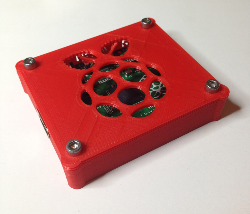
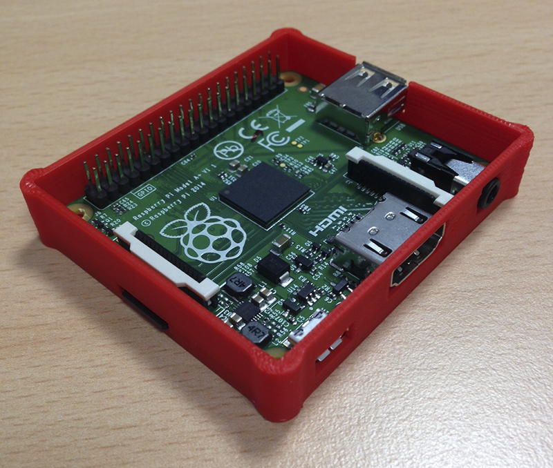
 The Raspberry Pi Model A+ is very cute. But it’s even cuter with it’s own 3D printed case. Here’s a case design for you to download and print yourself!
featuring the blog where you learn from my mistakes…
The Raspberry Pi Model A+ is very cute. But it’s even cuter with it’s own 3D printed case. Here’s a case design for you to download and print yourself!
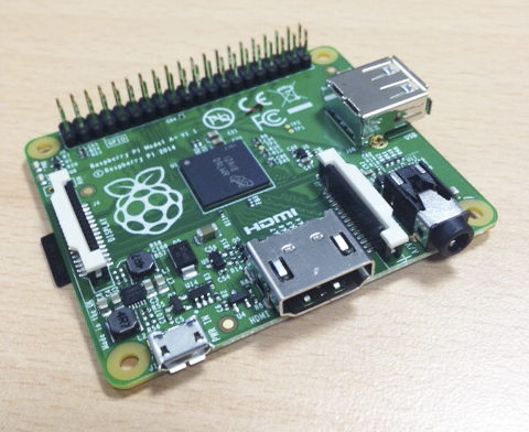 The Raspberry Pi foundation announced it’s latest member of the Raspberry Pi family, the Model A+. This is a departure from the usual credit card form factor, in that they’ve managed to knock off 20mm from the length, resulting in a very nice 65x56mm form factor.

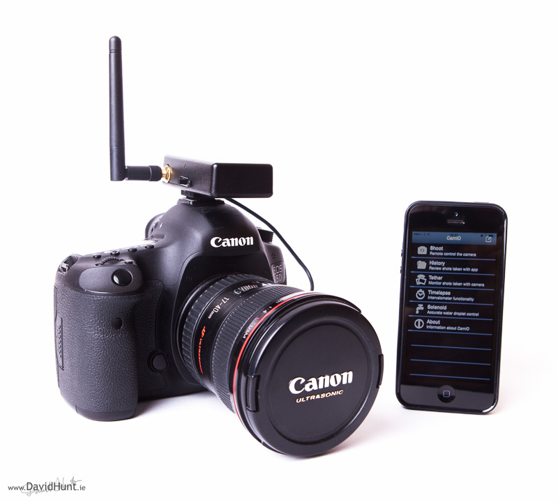
I’ve been working on camera hacks for a couple of year now. It started with the CameraPi, which was a Raspberry Pi mini-computer stuffed into an old battery grip for my Canon 5D Mark II Camera. Then came various variants on that, including a DIY time-lapse rail, the results you can see in the time-lapse section of this website. Theres’ also some water droplet photography, automated focus stacking, and even a bark activated door opener, not to mention the PiPhone.
Continue reading “First Intel® Edison project – DSLR Camera Controller”
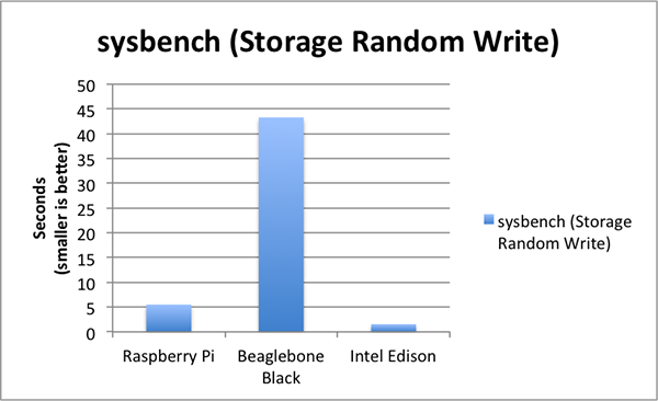
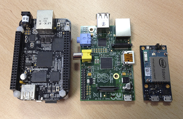 Recently I took delivery of an Intel Edison with a Mini-Breakout Board. I was awestruck by the size of the thing, but it was not until I started using it properly for a couple of projects that I noticed that it seemed a little bit ‘snappier’ than boards I’d used in the past (Raspberry Pi, Beaglebone Black). So I decided to do a little benchmarking.
Continue reading “Raspberry Pi, Beaglebone Black, Intel Edison – Benchmarked.”
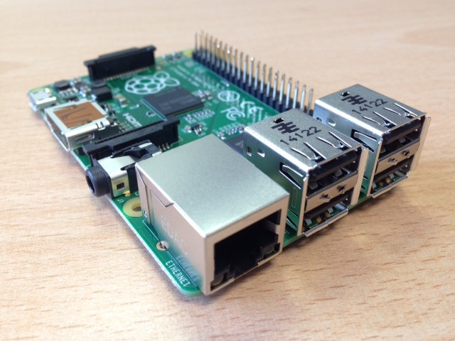 One day after launch, I got delivery of a Raspberry Pi model B+. Here’s a few pictures of it, plus a couple of side-by-side pics with the old Model B.
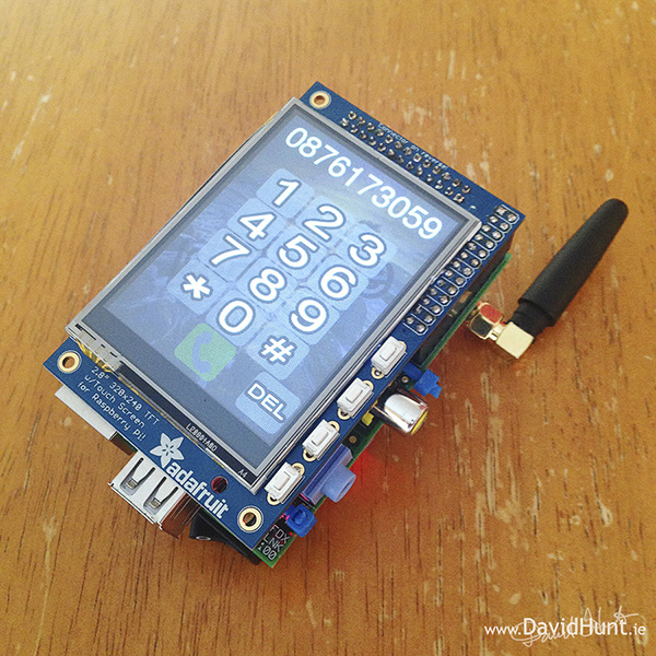
 Here’s my latest DIY project, a smartphone based on a Raspberry Pi. It’s called – wait for it – the PiPhone. It makes use an Adafruit touchscreen interface and a Sim900 GSM/GPRS module to make phone calls. It’s more of a proof of concept to see what could be done with a relatively small form factor with off-the-shelf (cheap) components. I don’t expect everyone to be rushing out to build this one, but I had great fun in doing it, as it builds quite nicely on my previous projects, especially the Lapse Pi, a touchscreen time-lapse controller, and uses most of the same hardware.
Continue reading “PiPhone – A Raspberry Pi based Smartphone”
Just a short post this time. When I saw this project on the Adafruit Learing System (learn.adafruit.com), I thought it was so cool that I had to build one myself. It’s a sound-activated LED tie!
There’s a great tutorial here: http://learn.adafruit.com/led-ampli-tie, so jump on over if you want to see how it’s made.
Just for kicks, I did a quick 28 second video of it in action. I can’t wait for the next hackerspace / coderDojo / work night out 🙂
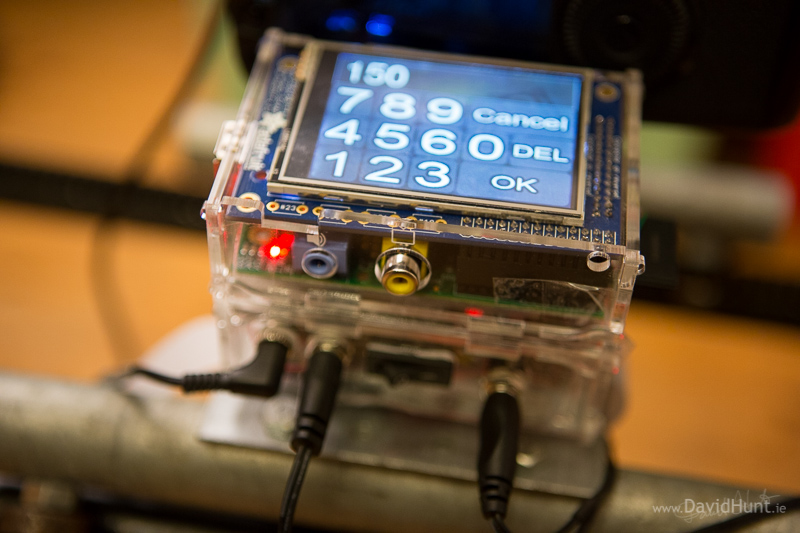 So here’s my latest Raspberry Pi project. It uses the PiTFT Mini Kit, which is a 320×240 2.8″ TFT display and Touchscreen from Adafruit Industries that fits neatly onto my Raspberry Pi, to control a user interface to drive the back-end time-lapse script I showed you in a previous blog article.
Continue reading “Lapse-Pi Touch – A Touchscreen Timelapse Controller”
 (DISCLAIMER: Not meant as a security solution or a lesson in good dog behavior. It’s an experimental proof of concept to play with the application of embedded computing to solve particular use cases)
Sleep deprivation has been driving me mad recently. And it’s all down to a new member of the family (kind of), our new dog. She barks at night when she’s left out. She barks early in the morning when she’s left in. So once I recognized the patterns of her barking, I realized that all I needed was something that would let her out when she needed to go for a pee, usually around 6:30 in the morning. I could do this with a timer switch and a door strike, but where’s the fun in that.
Continue reading “Pi-Rex – Bark Activated Door Opening System with Raspberry Pi”
 I’ve recently had the need to solder some small components at home, but don’t have a microscope, or even a decent magnifying glass. But then I thought that I’d a rather expensive DSLR and a pretty good macro lens, along with some extension tubes (allows closer focussing). Now I know that the camera has a Live-View facility (it’s a Canon 5D Mark III), but would the display be output easily to a monitor? Well, in the box that came with the camera, I found a cable which had a composite connector and some kind of A/V connector for the camera, so I set it up as shown in the pictures, a switched on the camera. The menu was displayed on the monitor, as hoped. Once I’d enabled live view and adjusted the settings so the exposure was OK, I zoomed into the display, first x5 and then x10. Each time the live view display was replicated on the monitor.